Hi
this question is a little long-winded, so please bear with me....
I recently hacked a cheap resistive touchpanel; the implementation was unsuccessful but I was intrigued by the practicalities of pulsing each axis to get continuous X-Y location data - each axis is rapidly switched between a read function and a 5v function. In the end the noisy data prevented further use.
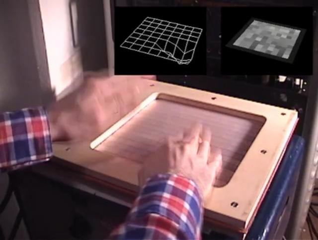
I am currently working on a 5x3 grid of DIY force sensors, which works well, giving me 15 discrete touch locations and Z-axis force data:
Following an idea by Randy Jones, who successfully implemented a multitouch FSR matrix:
I am considering extending the grid into an 8x8 matrix, which will give me 64 discrete locations, Z-axis force and greater opportunity for interpolation across the entire matrix.
My question is: can I 'hijack' the rapid switching idea from the resistive touchpanel (power the X axis, read the Y, then power the Y axis and read the X?) in my DIY FSR matrix.
There are 2 simple diagrams explaining my concept, here:
http://www.docstoc.com/docs/90785897/DIY-FSR-matrix
(I'm having trouble attaching/uploading picture files here).
My initial concept was for 8 strips of copper fabric (all connected to 5v) laid out in rows, then a layer of velostat, then 8 columns of copper fabric connected to the read inputs via pulldown resistors. It occured to me that I could only get ONE axis reading for this circuit (as depicted in the first diagram above); but would it be possible to get discrete X-Y touch location by rapidly alternating reading and powering to the circuit? I could easily build and code for this, but what I don't know is, how would I interpolate between reading X axis and Y axis to give me one reading (for each of the 4 points in the second diagram above)?
Thanks for bearing with me
Brendan
The bit you are not getting is the scanning of the strips you have connected to 5V. In the top diagram you want to make only one strip 5V and make the others high impedance, that is set them to inputs. Do the scan of the bottom readings and then, make the top strip next to the 5V also 5V and the original strip an input. In that way you get an array of 64 readings, the largest one will be the position of the touch.
Hi
thanks for replying. Maybe cos it's quite late at night, but i'm not sure I understand; I included the top diagram to demonstrate my intial thoughts. The proposed setup in that diagram might be powered thus:
set the bottom layer of columns to read (input);
set the top layer of rows to 5v;
(let voltage settle, c. 5ms);
set the top layer of rows to read;
set the bottom layer of columns to 5v;
and the second diagram is a simplified version of this (using only 2 columns and rows).
Do you mean that I might read continuously from the bottom layer of columns, if I alternate or cycle through the 5v rows?
Sorry, I appreciate you assuming I might not be a n00b, but, derpa derpa, I am. Could you clarify what you mean, perhaps in pseudo-code?
Thanks a million
Brendan
Do you mean that I might read continuously from the bottom layer of columns, if I alternate or cycle through the 5v rows?
Yes.
You need to do something like this.
set row 1 of the top to 5V and all the others to be inputs
read all 8 bottom columns and store
set row 2 of the top to 5V and all the others to be inputs
read all 8 bottom columns and store
set row 3 of the top to 5V and all the others to be inputs
read all 8 bottom columns and store
............ and so on
Then the biggest reading you get is the position of the touch. The x coordinate being the column number of the biggest reading and the y coordinate being the row that had 5V on it at the time.
The major snag with this sort of thing is the way the other conducting strips smear out or partially short the current flow from the 5V. But keep the strips thin and it should be fine.
Thanks Grumpy_Mike
I'll set this up over the weekend and get back to you with the results,
very helpful forum
Brendan
