Greetings everyone,
I must ask you, which is more badass? A single Arduino blinking a matrix of LEDS? Or an epic tower of Attiny85's, working together, blinking themselves and becoming the matrix?
Which is more expensive isn't the question. Price is everything, but that is posted at the end of this post. So I have had this project in mind of an "Attiny85 communication system" for quite awhile. I would like to produce this product to offer to the community, but first how about getting the communities feedback. If it is something they would consider as a consumer and what quality I should incorporate.
The base unit will consist of multiple (probably x2) separate Attiny85 boards that are designed in a manner that have the ability to interconnect with each other horizontally and vertically. No wires needed for communicating. These will be designed in a way you can stack as many as you like given you have the power/availability. If you want to go for a flat and vertical design. Somewhat like Legos, via female and male headers. Each Attiny board will be 5v regulated, so every 2 boards need 10v-15v (power is limited to each layer).
For example:
5v pwr in // Layer 3 | Processor 5 < - takes blink and moves another servo | missing board
10v pwr in // Layer 2 | Processor 3 <- takes blink and moves servo | Processor 4 <- receive - does something
10V pwr in // Layer 1 | Processor 1 <- blinks LED, HIGH and sends signal up^| Processor 2 <- sends signal
The entire purpose of interconnecting is this could be used for communicating via the I/O's to perform a task, or you can take a piece off as a separate Attiny85 board. Something of novelty but what else did we buy an Arduino for? 1-2 boards (or layer) will have an AC adapter, the other boards can be powered via the Vin/GND pins. The base unit will also come with a "programming shield" compatible for the Arduino UNO or other alike devices.
Roughly estimated net price is:
$21.50 per layer (2 Attiny85 boards)
I'm not very familiar with the BlinkM, but its seems sweet! That is the kind of quality I hope I can produce with this, but as of now I suspect hand made PCBs.
But to answer your question, sort of. Yes, by how the BlinkM's can communicate. But no, my intention with this is not to be only a display. All the I/O pins will be available with headers, whereas the BlinkM's pin are dedicated to its LED. Just as you may use a shield on your Arduino, except you could have one processor outputting information into two other possessors at the same time.
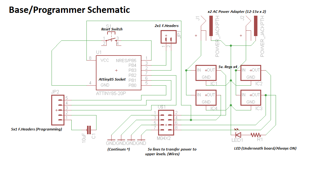
Meh... well my spring break comes to an end :[. Freakin' depressing lol, but here is the general schematic for the base unit. I tried to put it into an easier format for better understanding. (This is the unit everything else connects to when in considering it as a standalone network.)
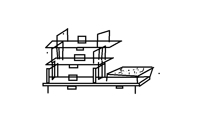
This is top view that should help explain what I mean about connectivity. I have also decided to add a flat ultra bright LED of the bottom of the board between pin D0 which will have a switch for on/off. Cheers
So . . . Stacking this many boards is freaking complicated while trying to avoid wires. How do you transfer 5v's to 5 shields stacked up on top of one and another while keeping a low center of weight distribution? Its going to be one unit so it needs to e stable. Cables anywhere past the 2nd level will make it wonky.
So all the power is on level 1, and you can use jumper cables to reach the other boards. (The expansions will have screw terminals to secure the power flow.) There will be 2 12v AC PSU's on the base as well, giving you a max of 4 levels in total. Hopefully that will suffice.
So here is the schematic for the base unit (The I/O's will change :P).
I'm currently talking with a gentleman about outsourcing the PCBs. They should be unique and pretty to look at. "/
Need your feedback on this. Being the expansions (higher level boards) are half the diameter of the base board. There is a little space above the 5v Regs. Would you think a mini bread board is a nice feature here. I think it adds to the self contained idea as well as you could host sensors and whatnot over there. I don't know let me know what you think. (PS I'm not a Paint artist :P)
The routing between components is too complicated. It isn't flowing due to all the overlapping connections and regulators. It's probably possible, but I can't do it. The result versus the amount of work this is taking isn't worth it.
I still have like 20 Attiny85's though. I'm just going to make a bunch of them (singles.)
It's a shame this didn't work out. Would it have been more feasible to keep the regulation off these boards, and supply at 5V to each board from a trusted external source?
dritchie0042:
I still have like 20 Attiny85's though. I'm just going to make a bunch of them (singles.)
You can in my opinion, never have too many ATTiny85s
Geoff
strykeroz:
It's a shame this didn't work out. Would it have been more feasible to keep the regulation off these boards, and supply at 5V to each board from a trusted external source?
dritchie0042:
I still have like 20 Attiny85's though. I'm just going to make a bunch of them (singles.)
You can in my opinion, never have too many ATTiny85s
Geoff
I'm not bummed about cutting this. I would have liked to see what it could have been, but its been a really good learning experience.
x4 5v DC adapters at the first level is feasible, but its not ideal. I'm not looking to settle. Each 5v reg. would have had a heatsink etc. I think it falls under preference in my opinion. you have to be proud of your product.
Adding I'm juggling this, work and college. I need to make time adjustments for what I can manage there as well.
Well, here's what I came up with. If you have any questions feel free, or if you see any errors in there let me know.
If your the lazy sort, I will be selling a few assembled boards on ebay soon (or side deal here), so keep an eye out for those. I'll post here when they are ready. Also feel free to use any of these for yourself if you wish.
GoForSmoke:
You can fit 3 Tiny85's on a single 24-pin socket. Each one can put a lot of attention on something.
But if all you want to do is blink lights the 1 Tiny and a set of shift registers will do for many leds.
That is a good idea, but how would you manage the routing of x3 5v regulators on a single sided copper clad board though? That was the real issue.
You don't need a separate regulator per chip. If you get a 5V regulated USB charger for power or any other 5V regulated (you can go with less BTW) power supply then you don't need any regulator on board. Just make sure that your supply has enough amps to run your project, those high-bright leds do suck current and IMO it's better to run them off power that doesn't go through the MCU.
3 on a socket just puts the pins closer. With a little creative work you won't need a PCB either. Just solder, add heatsinks as needed and maybe pot the works for durability and to save on an enclosure.
strykeroz:
What was the reason for multiplying the regulators? How many ATTinies was that to run?
GoForSmoke:
dritchie0042:
GoForSmoke:
You can fit 3 Tiny85's on a single 24-pin socket. Each one can put a lot of attention on something.
But if all you want to do is blink lights the 1 Tiny and a set of shift registers will do for many leds.
That is a good idea, but how would you manage the routing of x3 5v regulators on a single sided copper clad board though? That was the real issue.
You don't need a separate regulator per chip. If you get a 5V regulated USB charger for power or any other 5V regulated (you can go with less BTW) power supply then you don't need any regulator on board. Just make sure that your supply has enough amps to run your project, those high-bright leds do suck current and IMO it's better to run them off power that doesn't go through the MCU.
3 on a socket just puts the pins closer. With a little creative work you won't need a PCB either. Just solder, add heatsinks as needed and maybe pot the works for durability and to save on an enclosure.
Well, how many Attiny85's can I run on a single regulator without risking overheating it? Perhaps that is also an input question as well.
I choose 4 regs., for 4 micro processors because it was a safe assumption and guaranteed all would be "fed" properly. I want all Attiny's to have an output of 4+v.
Thanks for the tip on the power/leds btw. I would agree. (On the single boards above that is a lower power led).
dritchie0042:
Well, how many Attiny85's can I run on a single regulator without risking overheating it? Perhaps that is also an input question as well.
Depends on the regulator but in general, lots. At 5V and 8MHz, an ATtiny85 only draws 5mA. At 16MHz, 9mA. LEDs or whatever other loads are connected might actually account for the majority of the current.
If each board had a small regulator, rated for maybe 100mA, then they could maybe be used little more independently. When stacked they could be fed with 7-12V. OTOH, I don't see a lot wrong with one larger regulator feeding the whole stack, and that would cost less. Depends on what you want to do.
strykeroz:
What was the reason for multiplying the regulators? How many ATTinies was that to run?
Well, how many Attiny85's can I run on a single regulator without risking overheating it? Perhaps that is also an input question as well.
I choose 4 regs., for 4 micro processors because it was a safe assumption and guaranteed all would be "fed" properly. I want all Attiny's to have an output of 4+v.
The ATTiny85 has 200mA as the absolute maximum current across VCC & GND pins (section 21.1 of the datasheet) so if you're using a basic LM7805 linear voltage regulator which can output 1.5A the answer is "at least 7". In reality that is the absolute maximum consumption, which would be achieved when the output pins of the ATTiny are being used to source power (up to 40mA each) and wouldn't be where the uCs are comfortable operating for long periods. As noted above, it would be preferable the LEDs are fed power directly and the ATTiny is used to control rather than power them.
I would expect one voltage regulator to have covered 4x ATTiny85 with lots of headroom. The question of heat is a factor of what voltage you're regulating down from also. The higher the input voltage, the higher the power that is converted to heat by the linear regulator.
Cheers ! Geoff
The ideal would have leds and other loads not draw their operating power through the MCU's at all. That's what resistor-transistor pairs or driver chips are for.
My UNO has a regulator that gets -bypassed- when operating on USB power. It is only there for when I want to run from higher voltage sources which so far has been never. My Teensies don't have regulators at all and they work just fine.
You best choice is to make the regulators part of the power system. 3 Tiny's on a socket certainly don't call for 3 regulators. 3 bypass caps maybe but not 3 regulators.