hi there
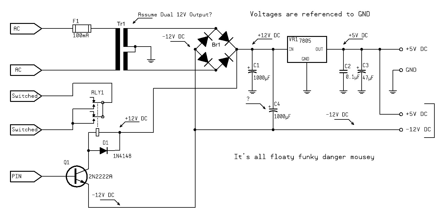
i have come up with this design for a power supply with two voltag outputs as you can see. i was wandering before i go and manufacture something if this will work or not?
also you can see a relay that is being powered off the 24v side but the trigger will be coming off an output off the arduino which is being powered off the 5v output. as theres two different neutrals for either power outputs i did not know if that would work? or if it would have to link the neutrals?
There are a couple of errors in your drawing.. 1. your note on the power transformer 12V.?. No 18 VAC X 2 or 36VAC CT. All circuit grounds must return to ground which is the center tap of the transformer... Not the - supply. The relay and transistor on the lower left of the drawing shows the ground returning to the - 12V side (which is going to be about - 18V Not 12V). To turn that transistor on requires a - voltage that is .7V less than the emitter or about -16Volts... Return the emitter of that transistor to ground, Not the - 12V dc supply . The Transformer CT IS GROUND... and it must also connect to the Arduino ground for a return path to the Arduino. C4 is improperly connected, ground the positive lead of that part. If that - 12V output must be -12V output then use a 7912.. You aren't going to have -12 V, more like -18 to -20V unloaded.
and that blue trace on the PCB that goes to the capacitor should be as big as the ones it connects to. Rework your drawings and present them again for inspection.... Please.
hi there thank you all for your replys and intrest
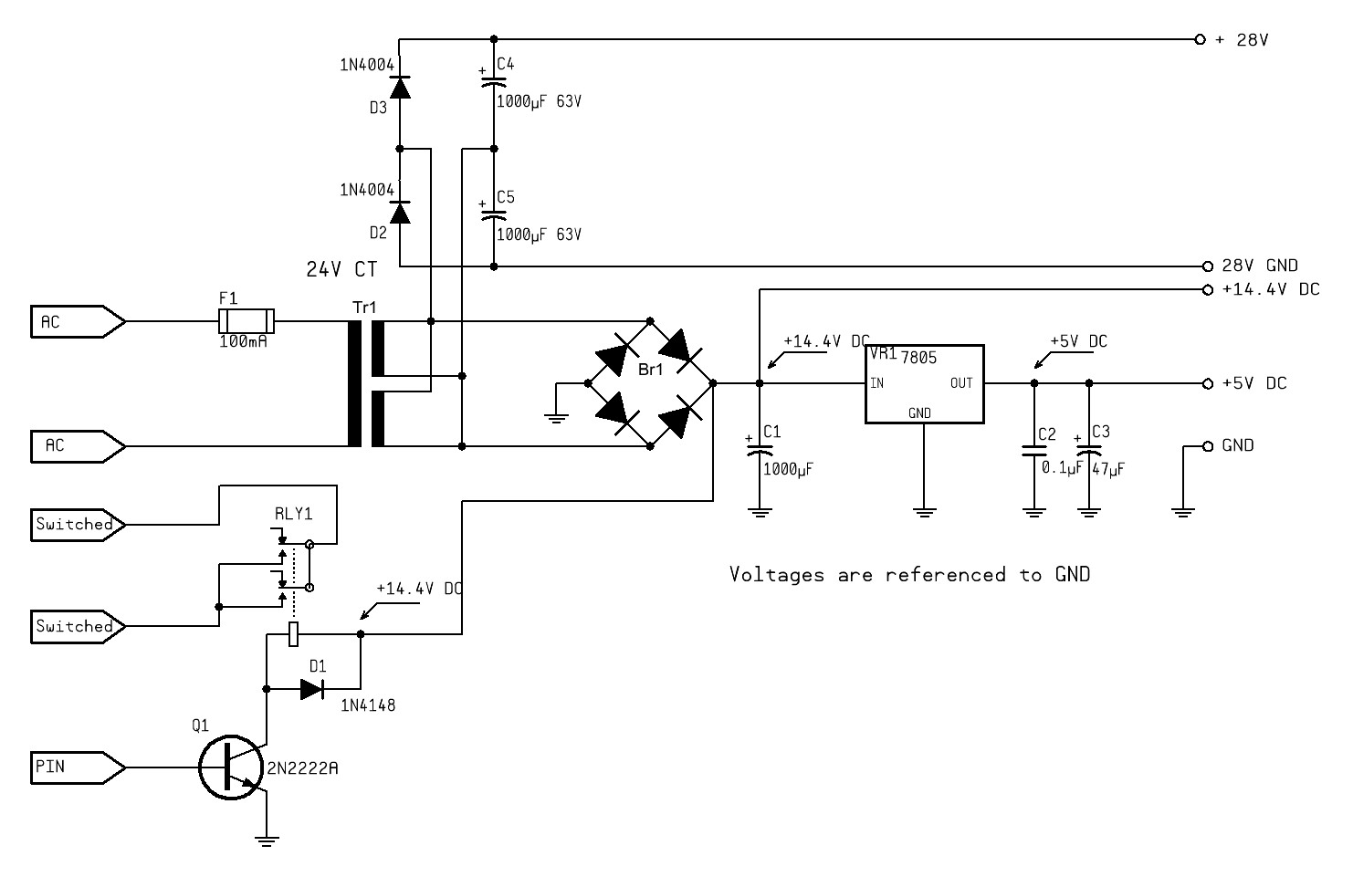
pwillard thanks for doing that schematic out of interest what software did you use to do that as it may be worth me upgrading from free hand lol
the transformer im using has an output of 24 volts as docedison said, offload i have seen this transformer sore upto 40V as the voltage regulator does not like this as most only go up to 35v hence why im trying to pick the voltage regulator off the centre tap so i only use 12v obviously that would be more on offload periods.
Docedison also thanks for your reply there are some things on there i might disagree on but some things i also agree on as it sounds like you know what your on about and have some experience on this it would be appreciated if you could do your own schematic as you can form it togehter in your own way to make it easier for us all to understand
Doc knows his stuff, he's done this for a living. FWIW, I don't disagree with anything he said. I'm not trying to be insulting, but based on the design you presented, if you disagree with any of his advice, you should probably double-check your work.
Again, not to be rude, but if you're the one benefiting from help, doing the schematics is your job. Even if it's your interpretation of someone else's input, you should be doing the legwork and asking "Like this?" to clarify if needs be.
once again thank you for your input pwillard, no the relay im using is a 24v relay which will handle 40v fine
hence why i needed the two ouput voltages