Does anybody have a schematics of Arduino using ATMEGA8? Is this arduino work similar to that of Arduino made from ATMEGA328? Please do reply for both ..
(deleted)
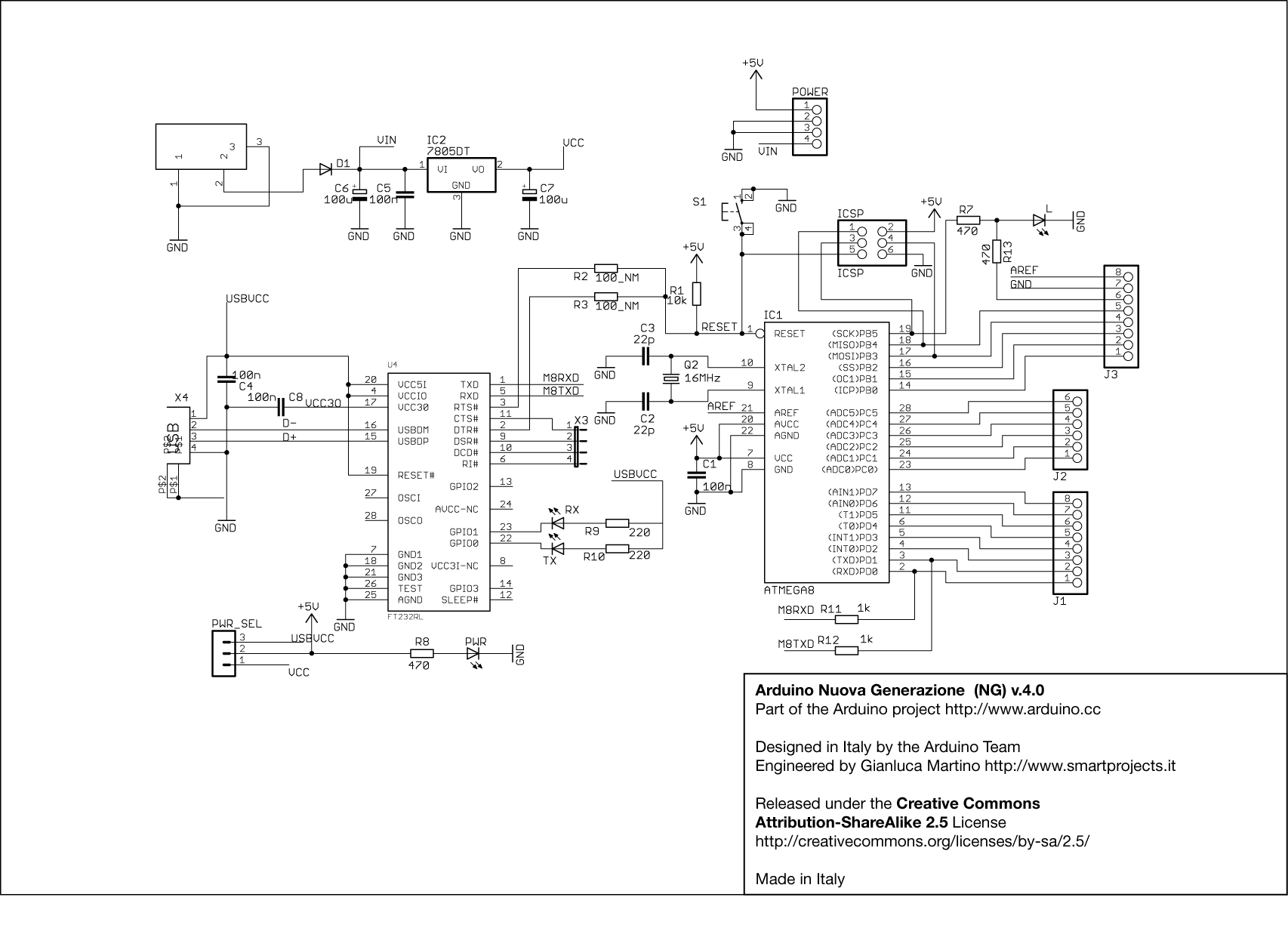
You can pop an atmega8 directly into any of the modern boards (uno, etc.) It's completely pin-compatible.
(although some of the pins that say "pwm" on the board won't be, any more.)
Thanx for schematics but can anyone explain these in that circuit?
What's that blank box(top left corner)?
Where this block gets connected to main circuit?
There are 2 Vin( one in power, other in that blank box). What is Vin?( in know its input to circuit) & where should it be connected to the atmega chip?
PWR_SEL(left bottom corner)?
P$1 P$2 (in USB)?
What's X3?
lastly where M8RXD & M8TXD should be connected?
deathbyte:
Thanx for schematics but can anyone explain these in that circuit?What's that blank box(top left corner)?
That's the external power connector. A 7-12vdc wall wart power module or a battery can plug into that connector if you are going to use external power for the board.
Where this block gets connected to main circuit?
It's shown be wired to the input of the on-board +5vdc regulator via D1 diode. The diode is to protect the board from mistake of applying reverse polarity voltage to the external connector.
There are 2 Vin( one in power, other in that blank box). What is Vin?( in know its input to circuit) & where should it be connected to the atmega chip?
Vin is the external voltage (7-12vdc), it wires to two places the input of the voltage regulator (IC2) and pin 1 of the shield power connector. There is no connection directly to the atmega chip as anything over +5vdc would destroy the chip.
PWR_SEL(left bottom corner)?
That's a jumper connector. You install a jumper clip to connect pin 1 to pin 2 when you want to power the board via the external power. You install the jumper clip to connect pin 2 to pin 3 if you wish to use USB voltage to power the board.
P$1 P$2 (in USB)?
These are connections to the metal shell of the USB connector and wire to ground.
What's X3?
These are trace pads run to the optional I/O pins of the serial converter chip. These I/O pins are not accessible to the Arduino, but with custom PC software one could utilize them.
lastly where M8RXD & M8TXD should be connected?
To pins 1 and 2 of the serial converter chip (U4) to resistors R11 and R12. These are the serial data signals to communicate with the atmega via the USB serial link.
Lefty
retrolefty:
deathbyte:
I still cant understand about Vin. Please Explain Is that having any specific value?
Is Vin an input to 'Power'? What should i do with Vin?
Are Vin & Vcc 2 separate power sources?What's r2 100_NM & r3 100_NM? Are they capacitors? What are its values?
What is difference between Vin,Vcc, Power connector?
That's the external power connector. A 7-12vdc wall wart power module or a battery can plug into that connector if you are going to use external power for the board.
I connect a 9V battery instead of wall wart module to supply power for it. If I do so should I connect another power source for Vcc?
What is value of Vcc?Vin is the external voltage (7-12vdc), it wires to two places the input of the voltage regulator (IC2) and pin 1 of the shield power connector. There is no connection directly to the atmega chip as anything over +5vdc would destroy the chip.
Also where is that "shield power connector"?