Arduino Due Construction Note #1 for Magnetic Musical Drum Set
May 29, 2013
Summary of Electronic Boards
Board #1 is Arduino Due with two Digital to Analog Converters (DAC)
Board #2 has level shifters for 9 volt digital port with seven digital outputs (14:20)
Board #3 has CD4051 Multiplexors, Sample and Hold, and VCO oscillators
Board #4 capacitors for 50 volts DC with light bulb pre-charge protection
Board #5 1000 watt transformer and rectifier power supply in a plastic bucket
Photograph Descriptions
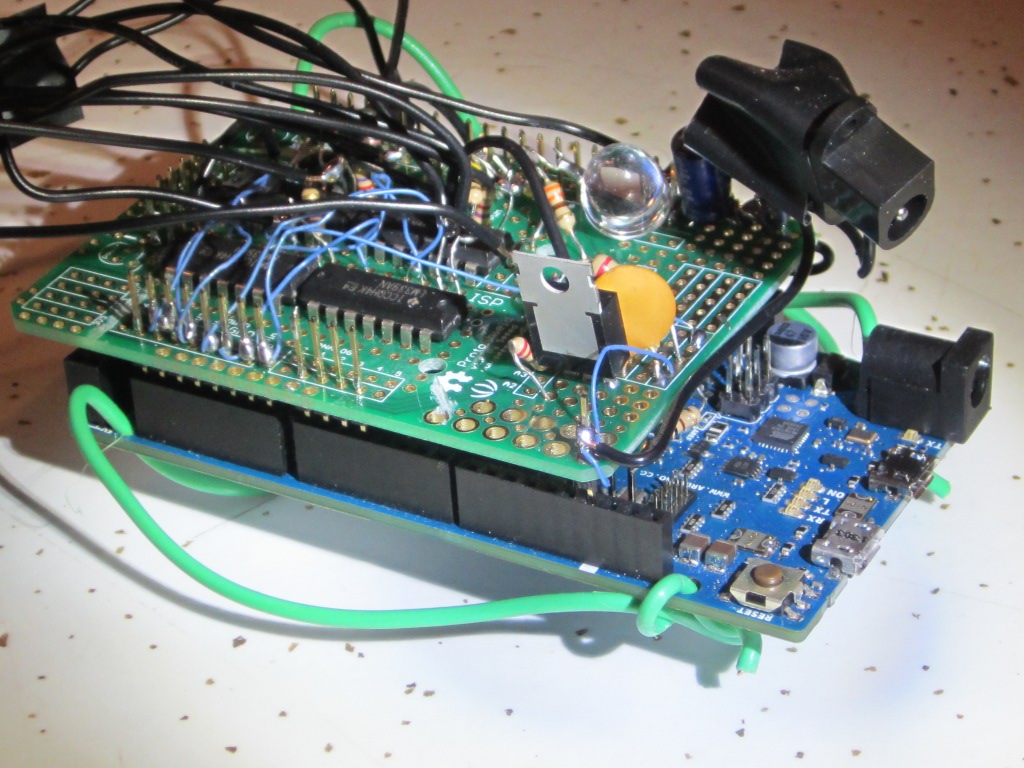
Board 1 and 2 were photgraphed together:
Board #1 is the Arduino Due. It has green wires to lift it above the workbench 1 cm. Purchased from Newark.
Board #2 is a Radio Shack Arduino experimenters board rotated 180 degrees and using connectors to board #1 for 24 digital pins and all analog pins from Due. The Radio Shack board costs $8: Seeed STR104B2P Protoshield Kit for Arduino. Board #2 has four LM339 comparator ICs, an LM317 regulator for 1.63 volt reference, red LED power indicator, type K power jack, DB25 connector output, decoupling capacitor for 9 volts. Also, the DAC0 and DAC1 wires have 470 ohms in series before the DB25 output connector in case of a short circuit.
Board #3 has DB25 connector input, 9 volts power with decoupling capacitor, three multiplexor (mux) chips for 18 channels for DAC0 to feed sample and hold amplifiers using five LM324 op amp chips. Six XR2209 Voltage Controlled Oscillators (VCO) are controlled by the sample and hold signals. Also one multiplexor chip CD4051 has 8 channels to control 8 voltage references for non-linear Wave Shapers. Two op amps amplify the DAC0 and DAC1 signals before they are used for anything. Board #3 was bought from Mouser as the PowerBoard-3U with copper on one side.
Board #4 : fifteen capacitors for 1000 watt power supply. The 4700uF capacitors hold the 50 volt DC supply for the custom non-linear amplifiers for the Magnetic Drum Set invention. Total capacitance 0.07 Farads. The capacitors are pre-charged through a 60 watt light bulb before full power is switched on to bypass the light bulb. The light bulb prevents the fuses from blowing on board #5 when power is turned on.
Board #5 : 1000 watt power supply with 60 volt RMS transformer and rectifier diodes, fan, smoke detector, and three fuses for 15 amps, 7.5 amps, 7.5 amps. In a plastic bucket. Hammond Manufacturing 182 series toroidal transformer ($190 from Newark). 1000 watts for driving six drumhead magnets.
DB25 connector pins
1 DAC0 after 470 ohm series resistor (470 = 3.3 volts / 7mA)
2 DAC1 after 470 ohm series resistor, range .55 volts to 2.75 volts, 12 bits
3 VSS
4 VCC 9 volts
14 Digital 14 Inhibit Mux 0 for Wave Shaper
15 Digital 15 Inhibit Mux 1 for Sample and Hold 0-7
16 Digital 16 Inhibit Mux 2 for Sample and Hold 8-15
17 Digital 17 Inhibit Mux 3 for Sample and Hold 16-17
18 Digital 18 = mux address A
19 Digital 19 = mux address B
20 Digital 20 = mux address C
Software was tested as follows:
Using the Arduino IDE Integrated Development Environment 1.5.2
/*
Mux_04.ino
for Mux selection test #4 May 28, 2013 Alan Folmsbee
This software for one magnetic drumhead is for minimally soldered boards 1, 2, and 3.
Seven Arduino digital pins 14:20 are used of 24 available pins on board #2.
INH inhibit and enable mux 1 with digital 15 = pin1
Select CD4051 channel from 8 using CBA "digital 20 19 18" = pins 6,5,4
Set 3 capacitor voltages with DAC0 on Mux 1 channels 0, 1, 2, range 0.55v to 2.75v
Inhibit other muxes 0 2 3 setting high "digital 14 16 17" as pins 0 2 3 */
const int mux_vco_pins[] = {14, 15, 16, 17, 18, 19, 20};
void setup(){
for (int i = 0; i<7; i++)
{
pinMode(mux_vco_pins*, OUTPUT);*
digitalWrite(mux_vco_pins*, HIGH);
_ analogWriteResolution(12);_
_ }_
_ / disabled all 4 muxes, default select channel 7, ABC = 111 /
/ three cd4051 multiplexors channel DAC0 to 18 signals for 6 drums using 3 oscillators each MUX 1:3 /
/ one cd4051 channels DAC1 to 8 signals to control the Wave Shaper for square root of sin (MUX 0) /_
_}_
void loop(){
_ / $$$$$$$$$$$$ Use 3 sample and hold capacitors for one drumhead /_
digitalWrite(mux_vco_pins[1], HIGH);
_ / used pin1 to deselect mux 1 for VCO 0,1,2 sample and hold capacitors 0,1,2 /_
_ analogWrite(DAC0, 4095);_
_ / set cap voltage for low pitch drum, range 0 to 4095 expected /
/ channel 0 binary code 000 : LOW LOW LOW !/_
digitalWrite(mux_vco_pins[4], LOW);
digitalWrite(mux_vco_pins[5], LOW);
digitalWrite(mux_vco_pins[6], LOW);
_ / next use pin1 to select this 8 channel IC /_
digitalWrite(mux_vco_pins[1], LOW);
_ delay(2);*_
_ /* $$$$$$$$$$$$$$$$$$$$$$$$$$$$$$$$$$$$$$$$$$$ /_
digitalWrite(mux_vco_pins[1], HIGH);
_ / used pin1 to deselect mux 1 for VCO 1 sample and hold capacitor 1 /_
_ analogWrite(DAC0, 1024);_
_ / set cap voltage for middle pitch drum with analog write to DAC0 /
/ channel 1 binary code 001 /_
digitalWrite(mux_vco_pins[4], HIGH);
digitalWrite(mux_vco_pins[5], LOW);
digitalWrite(mux_vco_pins[6], LOW);
digitalWrite(mux_vco_pins[1], LOW);
_ delay(4);*_
_ /* $$$$$$$$$$$$$$$$$$$$$$$$$$$$$$$$$$$$$$$$$$$ /_
digitalWrite(mux_vco_pins[1], HIGH);
_ / used pin1 to INHIBIT cd4051 mux 1 for VCO 2 sample and hold capacitor 2 /
/ set cap voltage for high pitch drum /_
_ analogWrite(DAC0, 0);_
_ / channel 2 binary code 010 /_
digitalWrite(mux_vco_pins[4], LOW);
digitalWrite(mux_vco_pins[5], HIGH);
digitalWrite(mux_vco_pins[6], LOW);
digitalWrite(mux_vco_pins[1], LOW);
_ delay(8);_
_}_
_
__

__

_*_
