I just got an RFID module and want to use it with my arduino UNO R3. Everytime try to use the Dumpinfo example, it says WARNING: Communication failure, is the MFRC522 properly connected?
I've literally checked every connection 20 times and I can't figure out what's wrong.
Can you please help me?
1 Like
I've literally checked every connection 20 times and I can't figure out what's wrong.
Post a picture of that wiring! Also it would help to see what sketch you're using. Post complete code!
/*
-
- Example sketch/program showing how to read data from a PICC to serial.
-
- This is a MFRC522 library example; for further details and other examples see: GitHub - miguelbalboa/rfid: Arduino RFID Library for MFRC522
- Example sketch/program showing how to read data from a PICC (that is: a RFID Tag or Card) using a MFRC522 based RFID
- Reader on the Arduino SPI interface.
- When the Arduino and the MFRC522 module are connected (see the pin layout below), load this sketch into Arduino IDE
- then verify/compile and upload it. To see the output: use Tools, Serial Monitor of the IDE (hit Ctrl+Shft+M). When
- you present a PICC (that is: a RFID Tag or Card) at reading distance of the MFRC522 Reader/PCD, the serial output
- will show the ID/UID, type and any data blocks it can read. Note: you may see "Timeout in communication" messages
- when removing the PICC from reading distance too early.
- If your reader supports it, this sketch/program will read all the PICCs presented (that is: multiple tag reading).
- So if you stack two or more PICCs on top of each other and present them to the reader, it will first output all
- details of the first and then the next PICC. Note that this may take some time as all data blocks are dumped, so
- keep the PICCs at reading distance until complete.
- @license Released into the public domain.
- Typical pin layout used:
-
- MFRC522 Arduino Arduino Arduino Arduino Arduino
- Reader/PCD Uno/101 Mega Nano v3 Leonardo/Micro Pro Micro
- Signal Pin Pin Pin Pin Pin Pin
-
- RST/Reset RST 9 5 D9 RESET/ICSP-5 RST
- SPI SS SDA(SS) 10 53 D10 10 10
- SPI MOSI MOSI 11 / ICSP-4 51 D11 ICSP-4 16
- SPI MISO MISO 12 / ICSP-1 50 D12 ICSP-1 14
- SPI SCK SCK 13 / ICSP-3 52 D13 ICSP-3 15
*/
#include <SPI.h>
#include <MFRC522.h>
constexpr uint8_t RST_PIN = 9; // Configurable, see typical pin layout above
constexpr uint8_t SS_PIN = 10; // Configurable, see typical pin layout above
MFRC522 mfrc522(SS_PIN, RST_PIN); // Create MFRC522 instance
void setup() {
Serial.begin(9600); // Initialize serial communications with the PC
while (!Serial); // Do nothing if no serial port is opened (added for Arduinos based on ATMEGA32U4)
SPI.begin(); // Init SPI bus
mfrc522.PCD_Init(); // Init MFRC522
mfrc522.PCD_DumpVersionToSerial(); // Show details of PCD - MFRC522 Card Reader details
Serial.println(F("Scan PICC to see UID, SAK, type, and data blocks..."));
}
void loop() {
// Look for new cards
if ( ! mfrc522.PICC_IsNewCardPresent()) {
return;
}
// Select one of the cards
if ( ! mfrc522.PICC_ReadCardSerial()) {
return;
}
// Dump debug info about the card; PICC_HaltA() is automatically called
mfrc522.PICC_DumpToSerial(&(mfrc522.uid));
}
This is the sketch and the wiring is exactly like:
- Typical pin layout used:
-
- MFRC522 Arduino Arduino Arduino Arduino Arduino
- Reader/PCD Uno/101 Mega Nano v3 Leonardo/Micro Pro Micro
- Signal Pin Pin Pin Pin Pin Pin
-
- RST/Reset RST 9 5 D9 RESET/ICSP-5 RST
- SPI SS SDA(SS) 10 53 D10 10 10
- SPI MOSI MOSI 11 / ICSP-4 51 D11 ICSP-4 16
- SPI MISO MISO 12 / ICSP-1 50 D12 ICSP-1 14
- SPI SCK SCK 13 / ICSP-3 52 D13 ICSP-3 15
*/
Use code tags!! Please edit your post and put code tags around the code, otherwise the forum system may hide stuff that may be relevant.
This is the sketch and the wiring is exactly like:
- Typical pin layout used:
- MFRC522 Arduino Arduino Arduino Arduino Arduino
- Reader/PCD Uno/101 Mega Nano v3 Leonardo/Micro Pro Micro
- Signal Pin Pin Pin Pin Pin Pin
- RST/Reset RST 9 5 D9 RESET/ICSP-5 RST
- SPI SS SDA(SS) 10 53 D10 10 10
- SPI MOSI MOSI 11 / ICSP-4 51 D11 ICSP-4 16
- SPI MISO MISO 12 / ICSP-1 50 D12 ICSP-1 14
- SPI SCK SCK 13 / ICSP-3 52 D13 ICSP-3 15
*/
That are five different wirings. And for the UNO there are two versions. I want to know which one you're using. You may post a picture of your setup.
How did you install the MFRC522 library?
I have the same problem, any solution ?
I have the same problem, any solution ?
Did you read the thread? No! Otherwise you've posted the information we requested.
I really don't have time to take a photo of the wiring, but please trust me, I have checked too many times, the wiring is exactly like it says in the sketch:
RST/Reset 9
SPI SS 10
SPI MOSI 11
SPI MISO 12
SPI SCK 13
I can't remember where exactly I got the library from, but it was most probably Github, so I'm sure it's the correct one.
I wonder if the problem is with these Chinese ones, as neither the module I got in my kit, nor the one I bought separately off eBay work (oddly enough, the eBay one worked correctly, but after I uploaded another sketch [still, with the same wiring], it didn't work anymore and displayed the error {not even the original sketch that it worked with before would work}). The eBay seller said he will resend it, but it's almost been about 2 months and nothing showed up (still praying).
But I think I just have bad luck, as my friend just got his (from a Romanian site, but still a Chinese fake) and it works. I might consider getting one from the same site, but what kind of draws me back is the fact that the shipping costs almost as much as the module (module= ~$5, shipping= ~3.75). It's not that much, considering it's 2-day shipping, so I guess I should just try my luck.
Btw, are we all sure the module has 5v logic levels and not 3.3v? The eBay seller says he doesn't know (wow).
Is the I2C pin of the chip (1) pulled low and EA (32) pulled HIGH?
I wonder if the problem is with these Chinese ones, as neither the module I got in my kit, nor the one I bought separately off eBay work (oddly enough, the eBay one worked correctly, but after I uploaded another sketch [still, with the same wiring], it didn't work anymore and displayed the error {not even the original sketch that it worked with before would work}). The eBay seller said he will resend it, but it's almost been about 2 months and nothing showed up (still praying).
That's always a problem with that cheap Chinese stuff on ebay. I only buy such stuff if all necessary material is provided (schematics, connection description, etc.).
Btw, are we all sure the module has 5v logic levels and not 3.3v? The eBay seller says he doesn't know (wow).
The chip accepts only 3V3 so a board advertised as an Arduino extension should include a level converter. I doubt that $5 boards include much additional circuitry. It might be even possible that the chip accepts the over-voltage for some time to die later on.
It has a reason we're asking for wiring diagrams/schematics here. There are so many different boards available, we cannot know them all. And with Chinese sellers you increase the risk that you get a not working fake (chip is simply a piece of plastic without silicone inside).
Is the I2C pin of the chip (1) pulled low and EA (32) pulled HIGH?
I don't know, my module is, of course, a breakout (SPI) and has no pin labeled "EA" and, of course, I can't do micro-soldering to "mod" it, so...
Do you need photos of it (the module, a specific component, the IC itself etc.)? Maybe someone better than me at this could figure it out.
If you want to use that board and you don't get schematics from your vendor you have to go the hard way and make the schematics by following the traces on the board. The cheap hardware sometimes comes at a price, unfortunately. A multimeter in the "Peep" mode often helps to find the correct traces.
Well, the seller has sent me a manual for it, but it's mostly in Chinese, I can't really do much with it, maybe you could help me.
¦·¦+-¦+˜+-¦¦_CN.pdf (268 KB)
RFID_API.pdf (66.2 KB)
1 Like
I understand absolutely no Chinese but the drawings show a board with UART connections. That doesn't look like an SPI version.
I found the English version of that manual: http://www.icstation.com/images/ICS/describe/4154/4154.rar.
There is also an ultra-simple sketch for the Arduino available at that site: http://www.icstation.com/product_document/Download/4154.zip
It shows you how to connect the board to a Mega and with the provided sketch you can see the tags in reach.
I guess you won't get happy with that module on an UNO, the example is for a Mega which has enough hardware serials, if you connect it to the UNO you loose the debugging serial channel. I guess it's cheaper to buy a new RFID reader than to upgrade to a Mega2560.
Attached is an image of my 2 boards. I'm pretty sure they are both SPI, please correct me if I am wrong. Maybe the manual is wrong, or even better, the seller doesn't even know what he is selling...
So the solution is to buy a new board and hope for the best?
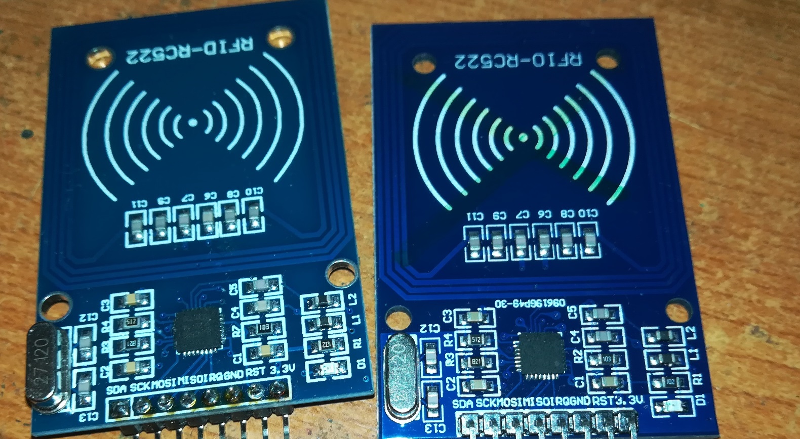
Watch carefully the chip pins, I received one board with some solder between two pins so it didn't work. I removed it and now the board works.
The soldering looks rather bad on the pictures.
In any way, connecting that board directly to an UNO might fry it.
RST/Reset 9
SPI SS 10
SPI MOSI 11
SPI MISO 12
SPI SCK 13
On your picture none of the pins is labeled SS, so which pin did you use for SS?
- MFRC522 Arduino Arduino Arduino Arduino Arduino
- Reader/PCD Uno/101 Mega Nano v3 Leonardo/Micro Pro Micro
- Signal Pin Pin Pin Pin Pin Pin
- RST/Reset RST 9 5 D9 RESET/ICSP-5 RST
- SPI SS SDA(SS) 10 53 D10 10 10
- SPI MOSI MOSI 11 / ICSP-4 51 D11 ICSP-4 16
- SPI MISO MISO 12 / ICSP-1 50 D12 ICSP-1 14
- SPI SCK SCK 13 / ICSP-3 52 D13 ICSP-3 15
Here it says "SPI SS SDA(SS) 10" so I just hooked up the pin labelled "SDA" to pin 10.
in any way, connecting that board directly to an UNO might fry it.
What do you mean?
What do you mean?
The MFRC522 is not 5V tolerant. The UNO has 5V on it's SPI pins but the MFRC522 must not get more than 3.6V (according to the datasheet). So you need a level converter.
Well, doesn't the module already have one? I mean, all the YouTube videos show these exact modules being used at 5V.
Domnulvlad:
Well, doesn't the module already have one?
No, it has not.
Domnulvlad:
I mean, all the YouTube videos show these exact modules being used at 5V.
pylon:
It might be even possible that the chip accepts the over-voltage for some time to die later on.
There are a lot of flat earth videos also and they show a similar level of expertise.
Domnulvlad:
Well, doesn't the module already have one? I mean, all the YouTube videos show these exact modules being used at 5V.
No there isn't, see schematic here
Unfortunately there are many videos and projects that are only a show, they works only for few minutes just for the show.
I used that board for testing without level shifher for tha same reason, many schematics doesn't have one, but thanks to Whandall I checked that and discovered I was wrong.
Alternative to a level shifter is a 3.3V board.