Graynomad:
I would use one of the TXB chips. Google for TXB010N where N is 1, 2, 4, 6 or 8 being the number of signals they can convert.
TXB010 comes in SMD packages only. You wouldn't happen to know of any bidirectional chips in DIP varieties? AFAIK they are unobtainium.
To OP, the CD4050 is a DIP package, cheap, and does 5V to 3V translation. Assuming you're using a digital signal, it's not high speed, and not I2C you don't need to worry about 3V to 5V translation -- the Arduino is fine recognizing 3.3V as a "high" signal. You could also just run the Arduino at 3.3V and not worry about it at all.
BSS138 is very inexpensive and a translator of that style is required with I2C signals.
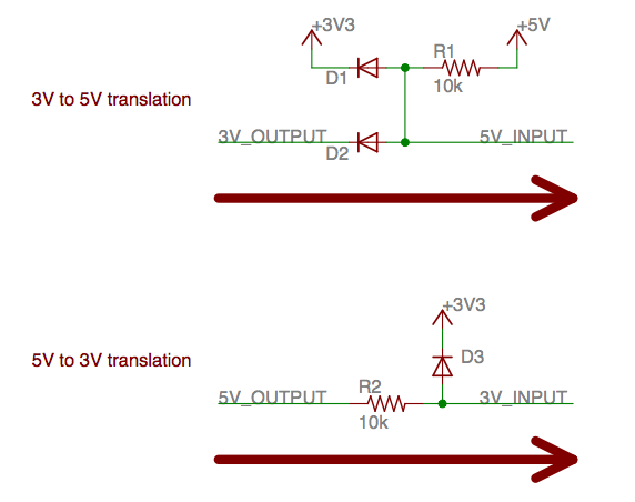
GoingForGold - The circuits should work. 10k seems a little high, but it's probably a good place to start. If you want it really bullet proof use a level shifter or opto-isolators.
Chagrin - Opto-isolators are available in DIP as are CD4504, CD40109, MC14504 or LTC1045 level shifters, but if you use the circuits the OP referenced, they don't need IC's at all.
I'd go with the BSS138 mosfet method in the Sparkfun PDF. While they are SMD, the come in a SOT-23 package so are dead easy to hand solder. They are also only about $0.06 apiece! If you order 25 of them from Mouser, they are less than a nickle each.
CrossRoads:
OP is making a PCB - what's wrong with SMD?
Nothing wrong with SMD; I was just asking if there are any bidirectional level translators in DIP packages. I'd been looking for something I could breadboard with but previously gave up on that quest. I understand there are other options but a DIP TXB010 would be a lot easier.
For low speed serial rx tx (ie up to 460kBaud) you need a simple resistor divider from 5VTX to 3V3RX and direct connection from 3V3TX to 5VRX.
See below: @500kBaud with high value resistors you get a perfect signal for rxtx..
For me, it came down to convenience. The TXB series is great if you have lots of of signal lines at one voltage being shifted to a different one - add a single TXB and you're done. Very clean board layouts can result and space savings are possible for any layout with more than 4 lines.
The BSS138 approach works great for single lines or when you don't mind the complexity that having three chips (BSS138 and two resistors) adds for each signal line. It's also great if you have lots of voltages to contend with - 1.8V, 3.3V, 4.2V, etc.
Where the TXB chips won't work is for I2C signal lines. They need a different translator, the TXS01xx series.
Constantin:
For me, it came down to convenience. The TXB series is great if you have lots of of signal lines at one voltage being shifted to a different one - add a single TXB and you're done. Very clean board layouts can result and space savings are possible for any layout with more than 4 lines.
The BSS138 approach works great for single lines or when you don't mind the complexity that having three chips (BSS138 and two resistors) adds for each signal line. It's also great if you have lots of voltages to contend with - 1.8V, 3.3V, 4.2V, etc.
Where the TXB chips won't work is for I2C signal lines. They need a different translator, the TXS01xx series.
The other problem with the TXB series is the driving IC has to source at least 2mA on the drive signal for it work properly. I ran into this issue trying to convert the signal from a GSM chip which couldn't source that high of a current. The TXS series has the advantage of working both on I2C (open-drain) signals and push-pull configurations (as long as the speed is below 20MHz).
Use the Sparkfun circuit... and use 2N7000's I've done it twice and BOTH worked perfectly. The 2N7000's can plug into an IC socket... Too. Not SMD. CHEAP and easy to do. See the NXP10441 App Note that I included with this post. It gooes through... with great detail what is necesssary. The IC's (the true Bi-Directional level shifters) are similar to the App note concept, just in a single package, SMD and difficult to deal with. The devices were designed to eliminate the necessity of placing all the parts required for the Mosfet idea. A GREAT idea for reduced production cost's BUT hardly an initial requirement here. When your device is debugged and you haave your first order for 1K pieces... Then BY ALL means use the IC's. The Logic gates, transmission gates (CD4066) and other ideas either are one way or they aren't capable of any current (@ 3V3 a CD4066 has about 500 ohms of series resistance... with that and a few hundred pF of board capacity... you have a great first order low pass filter... Not so great for I2C or SPI... As those signal bus's operate at a speed high enough to be crippled by a filter with a 100 KHz corner frequency. I modeled both the Mosfet and a Bi-Polar variant in MultiSim 11 before I choose the 2N700'0s. Both simulated perfectly and the Mosfet version looked real good when I looked at it with my O'scope... In Circuit between a BMP085 and an Uno Nice "Crispy Sharp" edges on both clock and data. It only takes 2 Mosfets (in TO-92 packages and the same pin lineup as a 2N3904 except gate for base, source for emitter and drain for collector) because you will already have or need the 3V3 and 5V pull-ups... So just 2 cheap parts. I've got about 20 of them... PM me If I can Help. AND READ the App note... Too.
{Edit Doc}
