You don't want shoot-through at all - nasty current spikes will generate heat in the transistors, possibly damage them and give more interference in any sensors.
Separate control of the two desired current paths in the H-bridge is one nice way to do this - use cross-connected topology:
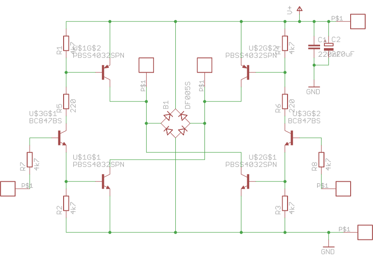
Each control input turns on one current path, you just ensure one is turned off before the other is turned on, allowing
enough deadtime for the transistors to de-saturate (1us is a good guess for this, so using digitalWrite will be slow enough).
Here the resistors R5 and R6 are chosen to provide adequate base drive for the supply voltage involved. Choosing low-saturation
voltage main transistors is going to help - the 2N2222 is an old device and nowhere near the state of the art, note. Finding transistors
with 0.1V Vsat at 1A will be worth it (you'll only lose 0.2V rather than 2V in the bridge).
But back to the problem, your stepper motor might be intended for chopper drive, not H-bridge drive, in which case using a
bridge is likely to both over-drive it and get only low speeds from it - what was the supply rail voltage for the scanner the motor
came from?