I am trying to control a relay using my attiny 2313 using my tv remote.. So the relay will be on when i press the tv remote for a certain time. It works well for a few minutes, until my attiny chip gets really hot, and it is messed up.. Anybody knows why?
Here is my code:
int led = 8;
int relay = 9;
int switchpin = 5;
long uptime = 0;
int count = 0;
int holdtime = 720;
int buttonval;
boolean buttonLast = false;
long time = 1450;

boolean ledval = false;

void setup(){
  pinMode(led, OUTPUT);
  pinMode(switchpin, INPUT);
}

void loop(){
  buttonval = (digitalRead(switchpin));
  if(buttonval == HIGH && buttonLast == LOW)
  {
    uptime = millis();
    count++;
  }
  if((millis() - uptime) > time){
   count = 0;
  }

  if(count > holdtime)
  {
    on();
    delay(2000);
    count = 0;


  }
  buttonLast = buttonval;


}

void on(){
  ledval = !ledval;
  digitalWrite(led, ledval);
  digitalWrite(relay, ledval);

}
Your status LED has no resistor in series, (lots of current then, and danger of burning something up)
I suggest a resistor in series with D2 (could draw extra current as wired).
I don't understand why the IR receiver is driving the XTAL1 pin, so I can't comment about that.
Thanks, i use 470 ohm resistor for pin 9 and pin 8 for led and the chip stops getting hot.. Right, pin 5 is for xtal1, i didnt realize that.. so i change it to pin 3..
But there's one more problem.. the amount of time to turn it off is not stable.. Sometimes it is off after 6 seconds, some other time only after10 seconds, while i only need 2 seconds to turn it on and it is stable.. Any ideas why?
Thanks
D2 is redundant, however you need a resistor in its place to limit the transistor base current (as well as the LED series resistor). I don't know why you are using a darlington transistor in that location, an ordinary NPN transistor would be better (i.e. lower saturation voltage, so the relay will get more of the 5V and switch more reliably).
Using pin 5 (XTAL1) as in input is perfectly OK because you are not using a crystal.
You should have a resistor in series with the BC557 base. However, you don't need the BC557 at all, you can just connect the IR sensor output direct to the attiny input pin, enable the internal pullup resistor, and amend the code to account for the input being active low instead of active high.
dc42:
D2 is redundant, however you need a resistor in its place to limit the transistor base current (as well as the LED series resistor). I don't know why you are using a darlington transistor in that location, an ordinary NPN transistor would be better (i.e. lower saturation voltage, so the relay will get more of the 5V and switch more reliably).
Using pin 5 (XTAL1) as in input is perfectly OK because you are not using a crystal.
You should have a resistor in series with the BC557 base. However, you don't need the BC557 at all, you can just connect the IR sensor output direct to the attiny input pin, enable the internal pullup resistor, and amend the code to account for the input being active low instead of active high.
Thanks again..
So, the schematic should be like this?
Also, any idea how to use input_pullup command for attiny?
That looks good, however you need to add a 0.1uF decoupling capacitor between the Vcc and Gnd pins of the attiny. Check that your relay needs less than 100mA current, otherwise you should use a transistor with a higher collector current rating than BC547, for example BC337 (or BC817 if you will be going SMD).
Are you going to include a 6-pin ICSP header so that you can program the chip in-situ? If so (or if you have anything else connected to the reset pin), I suggest adding a pullup resistor of 4.7K or 10K between the reset pin and +5V.
If the attiny core you are using doesn't support the INPUT_PULLUP mode of the pinMode function, then set the pinMode to INPUT and digitalWrite HIGH to the port - that will enable the pullup resistor.
dc42:
That looks good, however you need to add a 0.1uF decoupling capacitor between the Vcc and Gnd pins of the attiny. Check that your relay needs less than 100mA current, otherwise you should use a transistor with a higher collector current rating than BC547, for example BC337 (or BC817 if you will be going SMD).
Are you going to include a 6-pin ICSP header so that you can program the chip in-situ? If so (or if you have anything else connected to the reset pin), I suggest adding a pullup resistor of 4.7K or 10K between the reset pin and +5V.
If the attiny core you are using doesn't support the INPUT_PULLUP mode of the pinMode function, then set the pinMode to INPUT and digitalWrite HIGH to the port - that will enable the pullup resistor.
Thanks, i'll add the cap.. Just wondering why use the cap? (newbie here :)) I'll check the relay again.
No, i program my attiny through an arduino, but thanks for the info.
Okay, I'll try that...
IC pin 5 is PA0, i set it as in input.
dc42:
Since you have so many unused pins, why not use the attiny85 instead of the 2313?
Thanks for the advice, but for some reason, attiny2313 cost less than attiny85 here in my country. I guess because of the program space?
THANKS ALL, I will give update after i try what u guys suggested.
navivanuva:
No, i program my attiny through an arduino, but thanks for the info.
How, exactly? I'm guessing that you put it in a breadboard, program it using ArduinoISP, then move it to your standalone system. With an ICSP header, you can program or reprogram it in the same way, but you don't need to remove it from the circuit first - provided that you don't have too much of a load connected to the MISO and SCLK pins.
navivanuva:
Thanks for the advice, but for some reason, attiny2313 cost less than attiny85 here in my country. I guess because of the program space?
Interesting - which country? How about attiny25 or attiny45 then?
How, exactly? I'm guessing that you put it in a breadboard, program it using ArduinoISP, then move it to your standalone system. With an ICSP header, you can program or reprogram it in the same way, but you don't need to remove it from the circuit first - provided that you don't have too much of a load connected to the MISO and SCLK pins.
Interesting - which country? How about attiny25 or attiny45 then?
[/quote]
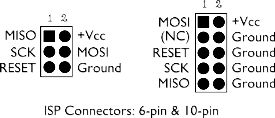
Yes you're right.. Ow nice! do u have the schematic for it?
I live in Indonesia. Havent check them, i'll definitely check them
Btw, i havent tried the circuit yet. I'll give u updates when i do.
Thanks
For the input_pullup, u suggested that i use digitalwrite(switchpin, HIGH) right? So when the ir reciever goes low, this pin also goes low? Eventhough it is set to high?
dc42:
How, exactly? I'm guessing that you put it in a breadboard, program it using ArduinoISP, then move it to your standalone system. With an ICSP header, you can program or reprogram it in the same way, but you don't need to remove it from the circuit first - provided that you don't have too much of a load connected to the MISO and SCLK pins.
Interesting - which country? How about attiny25 or attiny45 then?
Yes you're right.. Ow nice! do u have the schematic for it?
Sir, your program works fine with one relay, please help me if there is a similar type code for controlling more than one relay because in attiny the normal ir library doesn't work and i am stuck.
