We are using a 4 layer PCB for our product, and going for HASL lead free soldering with FR4 pcb material. May i know what TG to use for the PCB? What is the technical difference between Tg135 and Tg170.
May i also know what Tg and material does arduino use for their original boards
TIA
I have NO idea what you're talking about but I know how to use Google and I can read:
If working temperature of your product is higher than normal (130-140C), then have to use high Tg material which is > 170C. and popular PCB high value are 170C, 175C, and 180C. Normally the PCB Tg value should be at least 10-20C higher than working temperature of product
Now stop and think about it for a second. If the arduino was manufactured for hobbyists, would they need a glass temperature of 170 degrees Celsius ? Does that sound even REMOTELY necessary for a hobbyist environment or application ? Do you have to be a rocket scientist to figure that one out ?
Hi,
naveen4394:
We are using a 4 layer PCB for our product, and going for HASL lead free soldering with FR4 pcb material. May i know what TG to use for the PCB? What is the technical difference between Tg135 and Tg170.
May i also know what Tg and material does arduino use for their original boards
TIA
If you are designing a PCB and want information on PCB build parameters, contact a PCB manufacturer.
Why,because they are the people who will be dealing with your final product.
Tom.... ![]()
Why are you consulting arduimo ? Is your product for hobbyists ?
Do hobbyists projects operate at 170 degrees C ?
raschemmel:
Do hobbyists projects operate at 170 degrees C ?
Why yes, they do. For a few seconds anyway. 8^)
Why yes, they do. For a few seconds anyway. 8^)
Some OP's have built ovens but the electronics is not exposed to the oven heat because it is in a special enclosure , not in the oven. Others have built beer brewing equipment but I've never seen a post where the arduino is exposed to extreme heat.
Recently I got my prototype board done, they used FR4 Tg130. Frankly speaking I was not aware of all those tech terms and what the purpose of it at that time. I just relayed on the manufacture and their judgment.
I would suggest get a prototype done and revise it than thinking a lot.
For your reference, check one of my post about the pcb i done Aeroponic V3 – controlled by Arduino an overview | Sony Arouje
Did you ever remove the shipping seal from the piezo ?
What did the PCB job cost and how many boards ?
I havent removed the seal from peizo, the sound is very loud, so i kept the seal back ![]()
I did 2 PCBs, each cost me around $7.5 (450INR) including shipping.
Who did the PCB LAYOUT ?
I did it Raschemmel, it may not be a professional one. I am learning it by experimenting. Any way it serves my purpose for now. I checked with some professionals and they charged me a lot, so decided to do it my self.
Feel free to give any feedback.
I couldn't comment other than to say the traces look ok. I've never done PCB layout. I have ORCAD schematic capture experience but no board layout experience. If I need a hardwired circuit I just buy a protoboard and solder point to point. I've built over 50 in the past 35 years. I am curious what layout software you used.
This is my latest one
I normally use Eagle CAD or kicad. I etched several boards at home, single layer ones. I havent tried wired approach. Every thing started less than a year ago and still learning.
I may still attempt a layout one of these days...
I created an Arduino shield for programming Atmega32, link here Home made Arduino ISP Shield | Sony Arouje
I should have used a ZIFF socket like you did. Next version i will use a ZIFF socket.
I've had a lot of PCBs made, and reflow with SMD parts in a toaster over with high temp not exceeding 205C for 30-60 seconds.
I don't see anything here about Tg
http://support.iteadstudio.com/support/solutions/articles/1000156313-normal-condition-of-pcb-capabilities
nor do I recall seeing that at other manufacturer websites.
Once assembled, boards are operated under 85C as that is max the Atmega328P is rated for, unless more expensive Automotive grade parts are used with 125C as the top end. I have used these parts for cards designed to run in vehicles in Africa (along with appropriately rated crystals and other parts).
http://www.digikey.com/product-search/en/integrated-circuits-ics/embedded-microcontrollers/2556109?k=atmega328p&k=&pkeyword=atmega328p&FV=fff40027%2Cfff800cd%2C3f002df&mnonly=0&newproducts=0&ColumnSort=0&page=1&stock=1&quantity=0&ptm=0&fid=0&pageSize=25
I'm surprised you haven't gotten a PCB made up, Raschemmel. For what they cost from OSH park even if you make a goof its worth it. It makes everything look purdy. (even if it don't work).
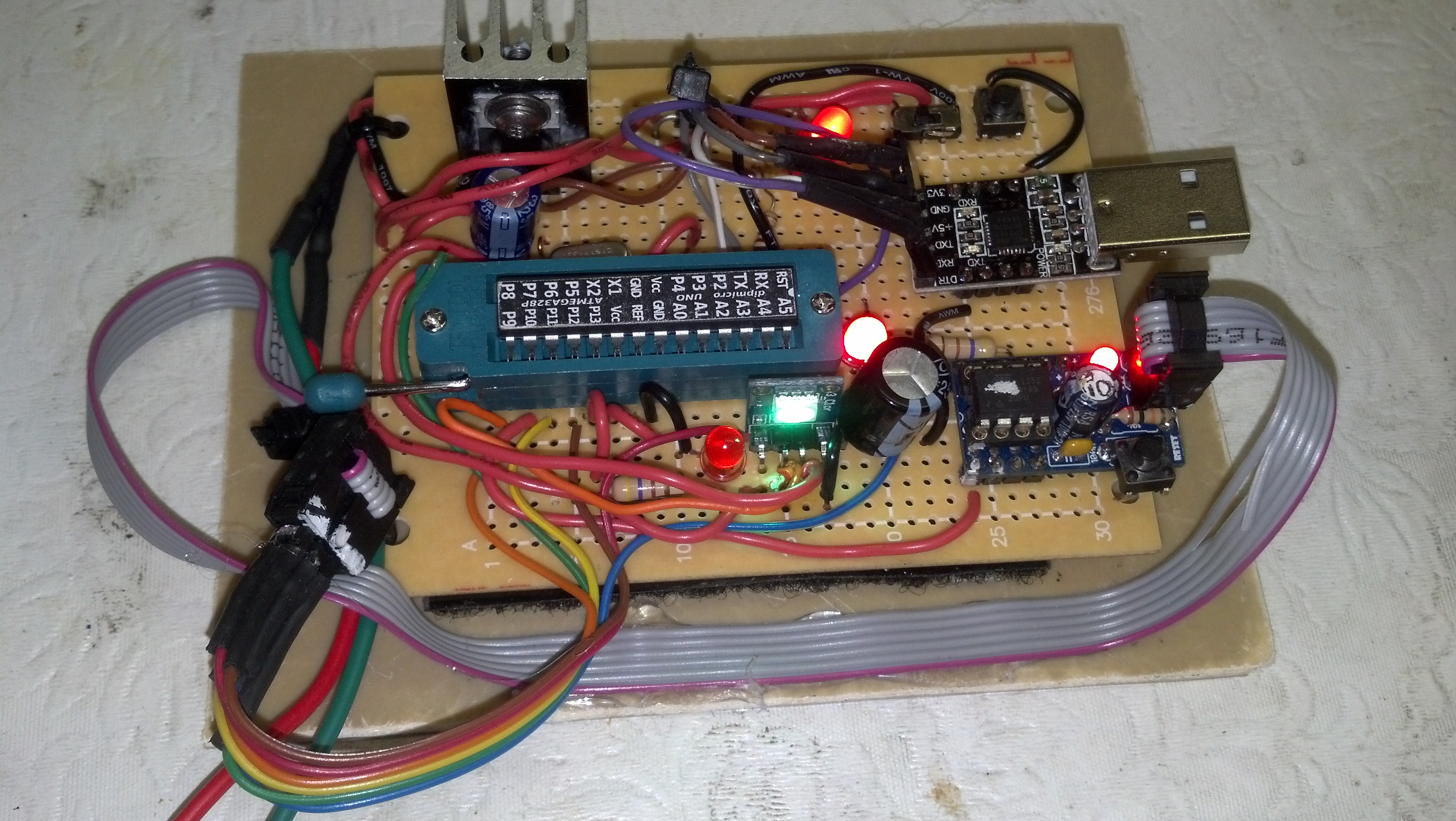
here is one I did...complete with amature soldering. the boards were $25 for three...
7-Did you do the layout ?.
yes. eagle cad, hobbiest version. The green wire and pull down resistors on the bottom are where i made a oops with the layout.