The "pin13" that the bootloader flashes is neither pin 13 of the atmega chip, nor pin 13 of the dip-like footprint of the nano, but rather the equivalent of the arduino "digital 13" pin, which is pb5.
Most real and "clone" nanos have the built-in led "L" on this pin. What actual hardware do you have?
I'm using a close Arduino Nano for the programmer. I'm using a QFP32-DIP28 IC test socket (for ATmega 8 AVR series) to connect to the target ATmega328P. I have omitted the test socket in my schematic.
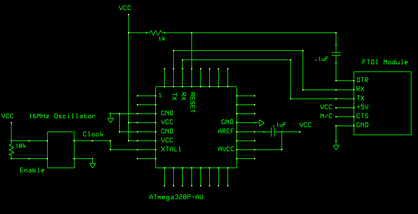
Your pull-up resistor on RESET should be 10k rather than 1k, but I would think that even 1k should work OK. It might interfere with auto-reset, though (but that shouldn't matter for the first "upload")
You should have bypass caps between Vcc and Gnd. The cap you have between Vref and Vcc is weird and wrong, but again, I don't think it should affect basic uploading.
I tried using the capacitor combo for the power supply pins as specified by the official arduino nano schematic. Surprisingly, this appears to interfere. I do not see in the ATmega datasheet where this is explicitly recommended.
Using a 40-100uF electrolytic cap on Vref works better, but this appears to not be the problem.
I suspect that my breadboard wire lengths may be causing my issues, but not a whole lot I can do about that.
I have ordered regular crystal oscillators to try next, but in theory that should not work as well as a resonator.
For now I'm giving up.
The good news is I discovered that the nano will operate with 3.3V applied to the 5V pin (bypassing the regulator).
So for a couple extra dollars, and a little bit of un-optimized board space, I can just use a knock-off nano plugged on top of my pcb projects.
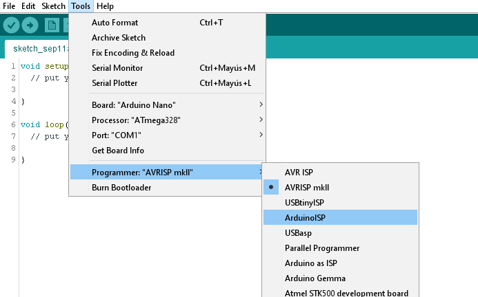
After you’ve put the bootloader on , load the “flash “
Example using the USB. If that works, then you have a bootloader in place. If you load a program via the FDTI then that over writes the bootloader .
I use NANO’s and set the board as “UNO”. ; then load the bootloader - that gives you optiboot ( smaller and allows you to use interrupts )