Hi!
I'm glad I've successfully joined the Arduino community last week. Now it's time for first problem to get on, as my ambitious project to make something a'la home automation is getting on.
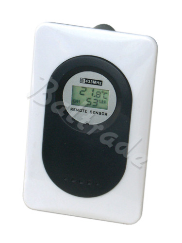
At the moment I stopped on reading the measurements of weather sensor.
As I was looking for working code to get the data from it, I've seen that it sends every 30-60 seconds the same binary code few times. As I googled I also assume that's because it doesn't use the check-sum (so it sends it repeatedly to make sure that station gets the measurements). It supports 3 channel and have a "force" button to send 'report' on demand (used while pairing with device).
Could you please provide a working code to get the measurements from RF433MHz reciever properly?
Or it's better to solder straight to sender before the RF module?
The next problem probably would be to find a pattern in which the data is hidden. It's much simplier than other weather stations because it only have temperature & humid data, not rain, wind etc.
If I manage, with your help hopefully, to get it working I'll surely like to share it for author of the library (Bitbucket) and community.
Just to clarify: I've spent whole night on googling and threads all around this forum.
None of the sensors used here (even on Deutsch forum, even if it was hard to understand) worked. That's why I start this thread.
It's not a complicated or secured transmission, the hardware inside looks simple. It just uses different pattern of data I guess.
I've found his thread with working code, but it has a bug.
Here's the code:
/*
 * Modified from "Thermor" DG950R Weather Station receiver v 0.3
 *
 * Receives data from a Weather Station receiver, via
 * a 433Mhz RF receiver connected to pin 8 of the arduino, and outputs
 * to serial.
 *
 * Based on the Practical Arduino Weather Station Receiver project
 * (http://www.practicalarduino.com/projects/weather-station-receiver).
 * For more info:
 * http://kayno.net/2010/01/15/arduino-weather-station-receiver-shield/
 *
 *
 */

#define INPUT_CAPTURE_IS_RISING_EDGE()    ((TCCR1B & _BV(ICES1)) != 0)
#define INPUT_CAPTURE_IS_FALLING_EDGE()   ((TCCR1B & _BV(ICES1)) == 0)
#define SET_INPUT_CAPTURE_RISING_EDGE()   (TCCR1B |=  _BV(ICES1))
#define SET_INPUT_CAPTURE_FALLING_EDGE()  (TCCR1B &= ~_BV(ICES1))

#define WEATHER_RX_LED_ON()         ((PORTD &= ~(1<<PORTD6)))
#define WEATHER_RX_LED_OFF()        ((PORTD |=  (1<<PORTD6)))

#define WEATHER_RESET()             { short_count = packet_bit_pointer = long_count = 0; weather_rx_state = RX_STATE_IDLE; current_bit = BIT_ZERO; WEATHER_RX_LED_OFF(); packet_start = false; }

#define TIMER_PERIOD_US             4
#define WEATHER_PACKET_BIT_LENGTH   19

// pulse widths. short pulses ~500us, long pulses ~1000us. 50us tolerance
#define SHORT_PULSE_MIN_WIDTH       420/TIMER_PERIOD_US
#define SHORT_PULSE_MAX_WIDTH       570/TIMER_PERIOD_US
#define LONG_PULSE_MIN_WIDTH        1420/TIMER_PERIOD_US
#define LONG_PULSE_MAX_WIDTH        1570/TIMER_PERIOD_US
#define BIG_PULSE_MIN_WIDTH        2920/TIMER_PERIOD_US
#define BIG_PULSE_MAX_WIDTH        3070/TIMER_PERIOD_US

// number of shorts in a row before the stream is treated as valid
#define SHORT_COUNT_SYNC_MIN        3
#define LONG_COUNT_SYNC_MIN         4

// states the receiver can be
#define RX_STATE_IDLE               0 // waiting for incoming stream
#define RX_STATE_RECEIVING          1 // receiving valid stream
#define RX_STATE_PACKET_RECEIVED    2 // valid stream received

#define BIT_ZERO                    0
#define BIT_ONE                     1

//byte locations of generic weather data in weather_packet[] array
#define WEATHER_STATION_ID          0
#define WEATHER_PACKET_TYPE         1

//types of packets
#define PACKET_TYPE_HUM             0
#define PACKET_TYPE_TEMP            1


#define DEBUG

// Type aliases for brevity in the actual code
typedef unsigned int       uint; //16bit
typedef signed int         sint; //16bit


uint captured_time;
uint previous_captured_time;
uint captured_period;
uint current_bit;
uint last_bit;
uint packet_bit_pointer;
uint short_count;
uint long_count;
uint weather_rx_state;

volatile bool packet_start = false;
volatile bool packet_end = false;
volatile bool ignore = false;

// byte arrays used to store incoming weather data
byte weather_packet[(WEATHER_PACKET_BIT_LENGTH)];
byte last_weather_packet[(WEATHER_PACKET_BIT_LENGTH)];

// packet counter - 4 identical packets in a row means the packet is valid
int packet_count = 0;


/* Overflow interrupt vector */
ISR(TIMER1_OVF_vect){                 // here if no input pulse detected
}

/* ICR interrupt vector */
ISR(TIMER1_CAPT_vect){

  // Immediately grab the current capture time in case it triggers again and
  // overwrites ICR1 with an unexpected new value
  captured_time = ICR1;

  //immediately grab the current capture polarity and reverse it to catch all the subsequent high and low periods coming in
  if(INPUT_CAPTURE_IS_RISING_EDGE()) {
    SET_INPUT_CAPTURE_FALLING_EDGE();      //previous period was low and just transitioned high
  }
  else {
    SET_INPUT_CAPTURE_RISING_EDGE();       //previous period was high and transitioned low
  }

  // calculate the current period just measured, to accompany the polarity now stored
  captured_period = (captured_time - previous_captured_time);

  // Analyse the incoming data stream. If idle, we need to detect the start of an incoming weather packet.
  // Incoming packet starts with a big pulse and the sequence 101010.
  if(weather_rx_state == RX_STATE_IDLE) {
    if( ((captured_period >= BIG_PULSE_MIN_WIDTH) && (captured_period <= BIG_PULSE_MAX_WIDTH))) {
      // received a big pulse - indicating the start of a packet
      packet_start = true;

    }
    else {

      if(((captured_period >= LONG_PULSE_MIN_WIDTH) && (captured_period <= LONG_PULSE_MAX_WIDTH)) && packet_start) {
        long_count++;
      }
      else if(((captured_period >= SHORT_PULSE_MIN_WIDTH) && (captured_period <= SHORT_PULSE_MAX_WIDTH)) && packet_start) {
        short_count++;
      }
      else {
        // not a long or short pulse, therefore not a valid bitstream
        WEATHER_RESET();
      }
    }
    if((short_count >= SHORT_COUNT_SYNC_MIN) && (long_count >= LONG_COUNT_SYNC_MIN)) {
      weather_rx_state = RX_STATE_RECEIVING;
    }
  }
  else if(weather_rx_state == RX_STATE_RECEIVING) {

    if(((captured_period >= SHORT_PULSE_MIN_WIDTH) && (captured_period <= SHORT_PULSE_MAX_WIDTH))) {
      weather_packet[packet_bit_pointer] =  0;
      packet_bit_pointer++;
    }
    else if(((captured_period >= LONG_PULSE_MIN_WIDTH) && (captured_period <= LONG_PULSE_MAX_WIDTH))) {
      weather_packet[packet_bit_pointer] =  1;
      packet_bit_pointer++;
    }


  }

  if(packet_bit_pointer > WEATHER_PACKET_BIT_LENGTH) {
    // full packet received, switch state to RX_STATE_PACKET_RECEIVED
    weather_rx_state = RX_STATE_PACKET_RECEIVED;
  }

  // save the current capture data as previous so it can be used for period calculation again next time around
  previous_captured_time = captured_time;

}

void setup() {
  Serial.begin(115200);

  DDRB = 0x2F;   // B00101111
  DDRB  &= ~(1<<DDB0);    // PBO(ICP1) input
  PORTB &= ~(1<<PORTB0);  // ensure pullup resistor is also disabled
  DDRD  |=  B11000000;    // (1<<PORTD6);   //DDRD  |=  (1<<PORTD7); (example of B prefix)

  //---------------------------------------------------------------------------------------------
  //ICNC1: Input Capture Noise Canceler         On, 4 successive equal ICP1 samples required for trigger (4*4uS = 16uS delayed)
  //ICES1: Input Capture Edge Select            1 = rising edge to begin with, input capture will change as required
  //CS12,CS11,CS10   TCNT1 Prescaler set to 0,1,1 see table and notes above
  TCCR1A = B00000000;   //Normal mode of operation, TOP = 0xFFFF, TOV1 Flag Set on MAX
  //This is supposed to come out of reset as 0x00, but something changed it, I had to zero it again here to make the TOP truly 0xFFFF
  TCCR1B = ( _BV(ICNC1) | _BV(CS11) | _BV(CS10) );
  SET_INPUT_CAPTURE_RISING_EDGE();
  //Timer1 Input Capture Interrupt Enable, Overflow Interrupt Enable
  TIMSK1 = ( _BV(ICIE1) | _BV(TOIE1) );

  //  attachInterrupt(0, rise, RISING);
  WEATHER_RESET();

  Serial.println("\"joshhawk\" Weather Station receiver v0.01");
  Serial.println("Ready to receive weather data");
}


/*
 * main loop
 */

void loop() {

  // weather packet ready to decode
  if(weather_rx_state == RX_STATE_PACKET_RECEIVED) {

    //#ifdef DEBUG
    Serial.println();

    for(int i = 0; i < ((WEATHER_PACKET_BIT_LENGTH)); i++) {
      Serial.print(weather_packet[i]);
      Serial.print(" ");
    }

    Serial.println();
    //#endif
    packet_start = true;
    WEATHER_RESET();

  }
}
Riva, you've worked out where was the bug in his code and he got it to work @ that thread.
Can you point what's wrong with it (or even fix it)? I don't have a clue...
You mentioned at that thread (Arduino Forum) this thing:
The code is a bit beyond me though I still think you only need to read rising or falling edge only and the timing between edges would determine start bit, 0 & 1 bits.
.
Ok, I did some more reading of the thread - he was getting packets recieved, I don't. Yet. Or they doesnt show up on Serial.
Can anyone share working code to get more easy-readable readings from RF reciever?
I helped/hindered in working out the decoding of the signal but the code that the person managed to find was (and still is) beyond me. I have done PIC16 software to decode Sony longitudinal time-code that is similar in format
but am still relatively new to ATmega architecture & programming and have not attempted anything like that (yet) using arduino.
The program that the original OP found in that thread seems to monitor both rising and then falling edge interrupts but I think it could have been done with just falling edge. I could not help any further as I don't have a RBxx receiver or a weather station to test any code with. I could maybe write some code if I someone supplied me with data from the RBxx receiver.
I've just soldered into "Data" and "Gnd" cables of RF transmitter.
Using code like:
int rfdataPin = 2;

void setup()                    // run once, when the sketch starts
{
  Serial.begin(9600);           // set up Serial library at 9600 bps
  pinMode(rfdataPin, INPUT);    // sets the digital pin as input to read
  Serial.println("RF433 Carrin arduino receiver startup");

}

void loop()                       // run over and over again
{
 int i;

  for (i = 0; i < 100; i++) {  // Used to create a CR point after 100 counts.
  Serial.print(digitalRead(rfdataPin));
  }

Serial.println(" ");    // Read the pin and display the value
//delay(100);
}
i get too much 0's on output when nothing is sent by device so I can't really measure proper bits.
Is there a code for a nicer output? So I could collect binary and readings from LCD about temp and hum.?
I've found a China producer of the sensor, maybe they will send me some info.
Anyway, at the moment - please, someone help me with code that detects "high" pulse starting with "1010", so I dont recieve all the zeroe's on the input.
I can't manage to do that... I'd really like to share some more info about this device for everyone, as the producer is in China so there will be probably more people interested in getting it working.
Yeah, the problem is I'm afraid of connecting 'data' pin to my soundcard without circuit for it.
And I couldn't fine any circuit except oscilloscope one (which I don't have all parts for).
Do you have any of these available? I have some old laptop with linux that I could play with.
Hi,
I've done this job a year ago and I used arduino for decoding
First you have to prepare the hardware:
open your sensor
find the modulator input
feed it into arduino with proper level change (I assume 0-3v => 0-5v)
The code I used was something like:
#define samples 700 //max 700
byte ms[samples];
boolean values[samples];
void setup() {
  pinMode(13, OUTPUT);
  pinMode(2, INPUT);
  Serial.begin(2400);
}
long lastChange, maxTime = 0;
bool previousValue;
void loop() {
  for (int i = 0; i < samples; i++)
  {
    values[i] = false;
    ms[i] = 0;
  }
  long start = micros();
  for (int i = 0; i <= samples; i++)
  {
    if (i == samples) i = 0;
    digitalWrite(13, (values[i] = digitalRead(2)));
    ms[i] = (byte)((micros() - start)/10);
    start = micros();
    while (values[i] == digitalRead(2))
    {}
    if((micros()-start) > 50000)
    {
      for (int k = i + 1; k < samples; k++)
      {
        Serial.print(k);
        Serial.print(":");
        Serial.print((int)ms[k]);
        Serial.print(":");
        Serial.println((values[k]?"true":"false"));
      }
      for (int k = 0; k <= i; k++)
      {
        Serial.print(k);
        Serial.print(":");
        Serial.print((int)ms[k]);
        Serial.print(":");
        Serial.println((values[k]?"true":"false"));
      }
      break;
    }
  }
  digitalWrite(13, LOW);
  delay(1000);
  digitalWrite(13, HIGH);
  delay(1000);
  digitalWrite(13, LOW);
  delay(10000);
}
After you manage to isolate one packet, take 2 consecutive readings with just one unit (in the least significant digit) difference in temperature or humidity. If your streams have one difference you don't have CRC, if you have 2 or mode differences you might have something like 011+1=100 or CRC or both. Here you need some luck.
After some hours of reverse engineering I come with the following code:
Did you manage to get this working? I did a quick hunt online for a similar looking wireless sender so I could hack it but found nothing suitable & cheap. I'm in the process of converting the audio captures joshhawk did for me in his thread into logic level samples so I can attempt to write an interrupt based receiver routine. I'm getting bit-streams from the one sample I have converted but time will tell if it's correct.
To have any real chance of helping you need to capture a transmission from your sensor and post it up here. It seems every make of sensor has a different way of transmitting the data.
I have knocked together a bit of test code that I just posted here Help me decode this 434mhz signal...? - #28 by Riva - Project Guidance - Arduino Forum As I don't have such a device to test it with it's really a shot in the dark.
I have also contacted the original thread poster joshhawk and he said the attached code below worked for his sensor. Hopefully yours is the same.
I might try to build voltage divider tonight.
I'm not sure how to do it by soldering into the sensor board, so I don't get signals from other sensors.
And I don't want to break the mic-in port in laptop (I don't have line-in in there).
Ideally you would tap into the data feeding the transmitter but I have no idea what point that would be on the pictures you posted without testing with a scope. There is a data line (yellow wire) that goes to another PCB. What does this PCB look like?
If you don't have a line level input on your laptop then the voltage divider you linked to is not much use.
andriej:
I might try on desktop PC, but I dont want to burn it so I have to be sure that those resistors are ok.
The yellow data wire is going straight to RF-transmitter module (it has a visible antenna also).
For a 5V input the 39K/10K you refer to gives a 1.02V output that should be okay. If you prefer to be cautious then try a 48K/10K that will drop the output to about 0.86V
Sounds like the yellow data wire may be a place to tap in, depends how smart the transmitter is as to if the data is raw transmitter on/off or a micro interface. Can you measure voltage when the unit transmits to be sure voltage is 0-5V range.
I tried to wire in to the transmitter - it sends same sound as the RF reciever gets, just much more quiet.
I'll be trying to pin to it now as it gives lower voltage. I couldnt get voltage divider to work, i get very noisy sound.
I managed to record one "test" button before my ears exploded ;-)) it's in attachment.
If you somehow manage to get code working for it (so i can harvest data from sensor), we might start debugging. http://dl.dropbox.com/u/619007/rf_oneread.wav - but it sounds corrupted near the one below.
Yep, managed to get few "normal" reads without the "transmit" button. It seems like it's send every minute. https://dl.dropbox.com/u/619007/few_reads_around24c_23wh_ch2.zip
temperature (i couldnt see the lcd while holding cable) was around 24.xC, humidity 23% and it was sent on second channel (and sensor have 1-2-3 CH option).
I didnt cut or modify the file - it's straight from audacity.
I hope it helps to get the "header" pulse for sketch...
I played it back slowed down few times - it sounds liek it sends 6 "pulses" every time. So it's like 6 (same?) messages for weather station, very near to each other.
You have managed to record some very clean signals. Do you have a receiver connected to your arduino or did you capture from the transmitter?
I have tidied up the wav file by splitting the 3x bursts you captured onto separate tracks and removing the long silences. I have attached the audacity project file so you can look at it. To have any real chance of decoding the data you really need to note the precise temperature/humidity of each sample you capture and try to capture over a large range of values.
The transmitter is repeating the data readings 6 times per burst transmission. Below is what one reading may decode to (I say may because the 0/1 bits may need inverting)
Sync 000101011110011 000011101101001000100100010 End
Sync 000101011110011 001011101101000000100100001 End
Sync 000101011110011 100011101101001000100101001 End
The first 15 bits are the same for all readings but may contain a channel number. You can confirm this by capturing data with the switch set to different channels.
I did it very simple way - one channel of jack [line-in] was held by yellow (DATA) cable. Other one was GND near battery.
I've used 2xRCA->stereo jack cable.
Hopefully I'll record some more (I have problems with sticking the wires to RCAs ;-)) and get readings also for CH1 and CH3 to see what's the difference.
At this point, with the pattern above - is it possible to modify your code to get the 0 and 1's from Serial with Arduino?
It'd be much easier to note down values of Temp. and Hum. using a notepad and ctrl-c ctrl-v. Even from a fridge etc.
