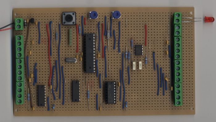
I have built a device using the Atmega 328P, based on the Arduino with motor shield, but have included a current measurement circuit that monitors the current through the L293D drivers and whose output is fed to an analogue pin of the 328. The current measurement is implemented with a sense resistor feeding a dual op-amp, half being an amplifier and half being a filter. It uses low side sensing and the design could have had the gain and filter combined but the design is simple and easy to follow / modify. References to the design tools are included in the write up.
The project is actually a 4 door chicken coop pop hole opener /closer. It has a Light Dependant Resistor to monitor light levels, pots to set the open/close delay at sunrise/sunset, switches to check the doors have shut and an LED to indicate status. The software monitors and averages the light level, checks when thresholds are crossed and works out the time of year and time of day from the length of the night. DC motors drive the doors open and closed. The current measurement gives an approximation of the load on the motor. This is good enough to decide if the door is fully open or blocked when closing.
The project could have many other uses requiring multiple drives, mixed analogue/digital sensors and/or current measurement.
The description is too wordy to paste here. There are several backup documents and everything is available at www.electrichen.co.uk The breadboard top view is attached. PVC covered wires were used because I didn't have any tinned copper wire to hand!