Data logging Motor Rotation pulse across 55 Treadmill motors with arduino

Hello everyone,
firstly let me apologise for my ignorance surrounding electronics, I'm an emerging experiences software engineer and to be quite frank, electronics has always been something I would ask my brother.. BUT he is useless. so.. I come asking advice on how I would implement the following situation.

I have to data log over an 8 hour period 50 Treadmill motors (Treadmills are Healthstream elite ESTM5 with the motor being a DC MOTOR 2.5HP Max speed is 22km/ph) and count each revolution from the motor as a pulse (this is where it gets hairy) and the anduino can then either A) store the value onto its removable flash or send a 8byte (64bit) array to some software that i will have reading in the signal via USB or hopefully using the Ethernet port on the Ethernet Mega that I have in my hand.

A few things I am not 100% sure how works, or how will work by design and that is, does a DC motor for treadmills have a data output for retrieve information from, and if so is this an analog or digital signal. Ideally I though i would need (if i was going the 8byte out to some software) that it would give me the following:

0ms 255-255-255-255-255-255-255-255 (no rotation pulses)
500ms 255-254-255-255-255-254 -255-255 (2 treadmills send a pulse)
501ms 255-255-255-255-255-255 -255-255 (all off again)
etc. etc.

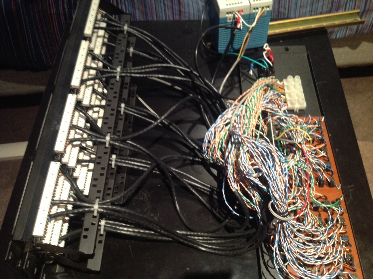
The current failing system is using a IOWarrior56 which is connected to a Ethernet Rack panel, which via USB reads the inputs of the treadmills via a small timing device similar (attached in image) that are connected to the treadmills and then wired into the Ethernet Rack. I believe there is a RS485 chip in the same module as the IOWarrior and the timing devices also have one as well. guessing the communication is then done by serial.

im quite happy to blow away the previous system as it is not performing, and I was hoping I could buy some sort of motor sensor (if the motors dont already have one) that will work well with the anduino, but anyones advice on what componentry/and or what methodology i need to get the most accurate pulses correctly concurrently over 50 treadmills would be amazing.

Sorry for the huge question, and hopefully someone is happy to help me out. My main headfritz at the moment is the best way of communicating from a treadmill motor (reading the rotations, not driving the motor) into a IO stream for me to capture the date. From there I am fine.

P.S if there is anyone in Melbourne Australia or Sydney Australia, who can help out with this issue, please respond back, as I am happy to pay for hands on advice/actual building of the system.

Thanks Robbie

Unless you put a Arduino + Ethernet shield in each treadmill, you are going to need some sort of sensor mechanism in each one. I would use an oscilloscope to check whether the devices shown in your board are generating good timing signals, to see whether you can still use them and just replace the IOWarrior with an Arduino + Ethernet shield. Also find a schematic or trace the wiring of those boards.

If you need new sensors, a Hall sensor and a magnet or two is generally the simplest way to count revolutions.

Amazing dc42, thanks for that. ill have a look and see if the board are generating good timing signals.

On the 55 treadmills I am lead to believe that the way we are currently connecting to the treadmills optical sensor to get a pulse every rotation.
Would this be correct? or do you think this is a hall sensor?

And one more question.. do i really need the RS232 chips (in my previous post i stated it was a RS485, it is actually a RS232 chip which seems to be talking between the treadmill timing devices and the current board which is housed in the same case as the IO Warrior? If i was to keep them, would that pose as an issue for when Aduino wants to recieve information back?

Thanks again, much appreciated.

Optical pickup is fine if it is working correctly, but may be affected by any dust and dirt that can get into that part of the treadmill.

You will need some sort of transmission mechanism between the treadmills and the Arduino. The board in your photo uses an opto-isolator, so if it really is RS232 then it must either be using the old current loop interface or some nonstandard interface. However, there is no way you will be able to receive 55 simultaneous RS232 signals on an Arduino.

If I were designing a new system, I would consider using a US1881 hall sensor with 2 magnets. This provides one pulse of 50% mark-space ratio per revolution, which is easy to monitor on the Arduino. I would use optical isolation at one or (probably) both ends. The US1881 can drive an opto isolator directly (with series resistor).

Is there a 5V supply available in the treadmill? I'm guessing there is, as something must be powering the existing boards.

What is the maximum RPM of the motor when the treadmill is being used?

So there is a 12V power supply that sits in the box with the IOwarrior currently that transmits power down 55 ethernet cables via a CAT5e connectors on each site, one for the smaller device shown earlier, and the other end if the reciever device which is currently the holding place of the IOWarrior.

either side has a RS232 chip for communication, and then the response from the RS232 chip is then passed directly into a single Input Pin on the IO Warrior. i presume i can do the exact same thing, but just replace the IOwarrior with the Anduino... or am i totally wrong about that :stuck_out_tongue:

Im just making sure i guess that the current solution is not over engineered, to the point where it is not functioning as well as it could be.

Really appreciate your answers, cant describe my current stress over this one device.

Attached photos of the internals of the current master device.

As I said before, an Arduino is the wrong device to receive 55 x RS232 channels concurrently. It might just be possible if the baud rate is very low, but the software would be complex. However, if the boards are silent most of the time and then send a single character over the RS232 when one motor rev occurs, then you only need detect the start of the character, and it becomes much easier.

If all the sensor boards are required to do is communicate that a motor revolution has occurred, then I would use a much simpler interface. The US1881 that I referred to earlier can work from a 12V supply.

You need to know the maximum motor RPM (hence the maximum pulse rate), to determine whether one Arduino can manage the data from 55 sensors concurrently.

Looks like your idea is a goer. Will get the US1881's tomorrow. The upper limit is 5500RPM @ 22km/ph normally user will do 18km/ph on the treadmill, but the device is being used in a competition scenario,
so the treadmill motors get pushed to the max.

Thanks for all your help, i may come back and ask more questions tomorrow.. :slight_smile: hopefully not.

5500rpm is nearly 100rpm, or 1 pulse every 10ms. That's faster than I was expecting. Here are a couple of issues you might face:

  1. Keeping the motor sufficiently well balanced when you glue magnets to a rotating part. A US1881 needs to see a N pole followed by a S pole, so you can glue 2 small magnets on opposite sides of a suitable rotating part. However, at 100 revs/sec, any imbalance will cause vibration. You might better of sticking with optical sensing, especially as the necessary hardware is already in place.

  2. The US1881 will generate a 1:1 square wave if you position the magnets diametrically opposite each other (so will a suitably-designed optical pickup). To register a pulse, then Arduino needs to see a high and a low state. So you need to sample and process each input at intervals of 5ms or below. I would aim for 3ms in case the pulses are not quite square. That's one input every 55us on average. That's easily doable, especially if you read all the inputs from a shift register using SPI at maximum rate. But if you are not careful, then any I/O or writing to flash that you do may cause pulses to be lost.