[SOLVED] Problems with SPI 12-bit Dual DAC (LTC1454)

Hi all,

I'm hoping someone can assist me with a problem I am seeing when using a LTC1454 12-bit DAC IC, with the Arduino (DUE) and the SPI bus.

This IC is a dual-output DAC, with data being sent to the chip over SPI as a 24-bit word. I have worked out a few phase-shifted sine tables in excel, and equated the corresponding bytes to send to the DAC to acheive this outputs. The code below shows these tables as a 2-dimensional, 360 point array.

I know I have configured the SPI bus correctly, as I am able to obtain a sine wave on the output of DAC-B of the IC. The code (below) shows a "for" loop, that steps through the same sine table for each DAC, however, the output of DAC-A appears to be corrupted on my scope trace!

That is to say, DAC-A and DAC-B are both being fed the same 12-bit words (I think!), but DAC-A appears to be receiving something different than expected. A screenshot below demonstrates what I am seeing, DAC-A is the high trace, DAC-B is below.

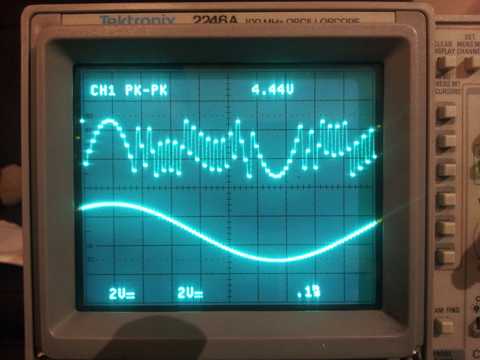
This looks like data courruption, rather than electrical clipping of the output, which is odd, as the code should be passing exactly the same words to each DAC register. I'm beginning to think I'm missing something pretty obvious in regard to timing or such, but I have poured over the datasheet and application note for this part for a few hours now, and I still can't see what it is I'm missing!

I would be incredibly grateful if one of you fine people could point out the silly mistake I'm making, or for any advice / input on this matter!

Kind regards,

Tom

Here's my code; some things to note are;

  • I'm using the extended SPI functionality provided by the DUE, in case anyone is wondering about the extra argument in SPI.transfer
  • I'm pretty sure the bitMath involved in the feedback portion of the code is not correct, but it is representative of the scope trace when graphed, and I'm too frustrated to improve upon it right now I'm afraid!
// Name:Driver
// Version A 0.1
// Tom Fleet, Jan, 2013
// Board Type: Arduino DUE (SAM3 Core)
// Description:
// Uses 2, dual 12-bit DAC's (LTC1454's) and 3 phase-shifted sine look-up tables.
// The lookup values are paased to the DAC's through the DUE's extended SPI interface.

#include <SPI.h>

#define LT1454_CS 4    //LT1454 Chip Sel Pin.
#define LT1454_CLR 5   //LT1454 CLR Pin.
#define button 53      //Active low tactile switch on digital pin 53, for manual stepping.

#define DEBUG 0        //debug flag to enable Serial output, etc.

//12 bit Sine LUT.
const int sine1Hex[2][360] = {// Table 1: Phase Shift = 0 degrees.
  //sineHex[0] = MSB,
  //sineHex[1] = LSB
                          {0x08,0x08,0x08,0x08,0x08,0x08,0x08,0x09,0x09,0x09,0x09,0x09,0x09,0x09,0x0A,0x0A,0x0A,0x0A,0x0A,0x0A,0x0A,0x0A,0x0B,0x0B,0x0B,0x0B,0x0B,0x0B,0x0B,0x0B,0x0C,0x0C,0x0C,0x0C,0x0C,0x0C,0x0C,0x0C,0x0D,0x0D,0x0D,0x0D,0x0D,0x0D,0x0D,0x0D,0x0D,0x0D,0x0E,0x0E,0x0E,0x0E,0x0E,0x0E,0x0E,0x0E,0x0E,0x0E,0x0E,0x0E,0x0E,0x0F,0x0F,0x0F,0x0F,0x0F,0x0F,0x0F,0x0F,0x0F,0x0F,0x0F,0x0F,0x0F,0x0F,0x0F,0x0F,0x0F,0x0F,0x0F,0x0F,0x0F,0x0F,0x0F,0x0F,0x0F,0x0F,0x0F,0x0F,0x0F,0x0F,0x0F,0x0F,0x0F,0x0F,0x0F,0x0F,0x0F,0x0F,0x0F,0x0F,0x0F,0x0F,0x0F,0x0F,0x0F,0x0F,0x0F,0x0F,0x0F,0x0F,0x0F,0x0F,0x0F,0x0F,0x0F,0x0F,0x0F,0x0E,0x0E,0x0E,0x0E,0x0E,0x0E,0x0E,0x0E,0x0E,0x0E,0x0E,0x0E,0x0E,0x0D,0x0D,0x0D,0x0D,0x0D,0x0D,0x0D,0x0D,0x0D,0x0D,0x0C,0x0C,0x0C,0x0C,0x0C,0x0C,0x0C,0x0C,0x0B,0x0B,0x0B,0x0B,0x0B,0x0B,0x0B,0x0B,0x0A,0x0A,0x0A,0x0A,0x0A,0x0A,0x0A,0x0A,0x09,0x09,0x09,0x09,0x09,0x09,0x09,0x08,0x08,0x08,0x08,0x08,0x08,0x08,0x07,0x07,0x07,0x07,0x07,0x07,0x07,0x07,0x06,0x06,0x06,0x06,0x06,0x06,0x06,0x05,0x05,0x05,0x05,0x05,0x05,0x05,0x05,0x04,0x04,0x04,0x04,0x04,0x04,0x04,0x03,0x03,0x03,0x03,0x03,0x03,0x03,0x03,0x03,0x02,0x02,0x02,0x02,0x02,0x02,0x02,0x02,0x02,0x02,0x01,0x01,0x01,0x01,0x01,0x01,0x01,0x01,0x01,0x01,0x01,0x01,0x01,0x00,0x00,0x00,0x00,0x00,0x00,0x00,0x00,0x00,0x00,0x00,0x00,0x00,0x00,0x00,0x00,0x00,0x00,0x00,0x00,0x00,0x00,0x00,0x00,0x00,0x00,0x00,0x00,0x00,0x00,0x00,0x00,0x00,0x00,0x00,0x00,0x00,0x00,0x00,0x00,0x00,0x00,0x00,0x00,0x00,0x00,0x00,0x00,0x00,0x00,0x00,0x00,0x00,0x00,0x00,0x00,0x00,0x01,0x01,0x01,0x01,0x01,0x01,0x01,0x01,0x01,0x01,0x01,0x01,0x01,0x02,0x02,0x02,0x02,0x02,0x02,0x02,0x02,0x02,0x02,0x03,0x03,0x03,0x03,0x03,0x03,0x03,0x03,0x03,0x04,0x04,0x04,0x04,0x04,0x04,0x04,0x05,0x05,0x05,0x05,0x05,0x05,0x05,0x05,0x06,0x06,0x06,0x06,0x06,0x06,0x06,0x07,0x07,0x07,0x07,0x07,0x07,0x07,0x07},
                          {0x23,0x46,0x6A,0x8E,0xB1,0xD5,0xF9,0x1C,0x3F,0x63,0x86,0xA9,0xCC,0xEE,0x11,0x33,0x56,0x78,0x9A,0xBB,0xDD,0xFE,0x1F,0x40,0x60,0x81,0xA1,0xC0,0xE0,0xFF,0x1E,0x3C,0x5A,0x78,0x95,0xB2,0xCF,0xEC,0x8,0x23,0x3E,0x59,0x73,0x8D,0xA7,0xC0,0xD8,0xF1,0x8,0x1F,0x36,0x4C,0x62,0x77,0x8C,0xA0,0xB4,0xC7,0xDA,0xEC,0xFE,0xF,0x1F,0x2F,0x3F,0x4D,0x5C,0x69,0x77,0x83,0x8F,0x9A,0xA5,0xAF,0xB9,0xC2,0xCA,0xD2,0xD9,0xDF,0xE5,0xEB,0xEF,0xF3,0xF7,0xFA,0xFC,0xFD,0xFE,0xFF,0xFE,0xFD,0xFC,0xFA,0xF7,0xF3,0xEF,0xEB,0xE5,0xDF,0xD9,0xD2,0xCA,0xC2,0xB9,0xAF,0xA5,0x9A,0x8F,0x83,0x77,0x69,0x5C,0x4D,0x3F,0x2F,0x1F,0xF,0xFE,0xEC,0xDA,0xC7,0xB4,0xA0,0x8C,0x77,0x62,0x4C,0x36,0x1F,0x8,0xF1,0xD8,0xC0,0xA7,0x8D,0x73,0x59,0x3E,0x23,0x8,0xEC,0xCF,0xB2,0x95,0x78,0x5A,0x3C,0x1E,0xFF,0xE0,0xC0,0xA1,0x81,0x60,0x40,0x1F,0xFE,0xDD,0xBB,0x9A,0x78,0x56,0x33,0x11,0xEE,0xCC,0xA9,0x86,0x63,0x3F,0x1C,0xF9,0xD5,0xB1,0x8E,0x6A,0x46,0x23,0xFF,0xDB,0xB8,0x94,0x70,0x4D,0x29,0x5,0xE2,0xBF,0x9B,0x78,0x55,0x32,0x10,0xED,0xCB,0xA8,0x86,0x64,0x43,0x21,0x0,0xDF,0xBE,0x9E,0x7D,0x5D,0x3E,0x1E,0xFF,0xE0,0xC2,0xA4,0x86,0x69,0x4C,0x2F,0x12,0xF6,0xDB,0xC0,0xA5,0x8B,0x71,0x57,0x3E,0x26,0xD,0xF6,0xDF,0xC8,0xB2,0x9C,0x87,0x72,0x5E,0x4A,0x37,0x24,0x12,0x0,0xEF,0xDF,0xCF,0xBF,0xB1,0xA2,0x95,0x87,0x7B,0x6F,0x64,0x59,0x4F,0x45,0x3C,0x34,0x2C,0x25,0x1F,0x19,0x13,0xF,0xB,0x7,0x4,0x2,0x1,0x0,0x0,0x0,0x1,0x2,0x4,0x7,0xB,0xF,0x13,0x19,0x1F,0x25,0x2C,0x34,0x3C,0x45,0x4F,0x59,0x64,0x6F,0x7B,0x87,0x95,0xA2,0xB1,0xBF,0xCF,0xDF,0xEF,0x0,0x12,0x24,0x37,0x4A,0x5E,0x72,0x87,0x9C,0xB2,0xC8,0xDF,0xF6,0xD,0x26,0x3E,0x57,0x71,0x8B,0xA5,0xC0,0xDB,0xF6,0x12,0x2F,0x4C,0x69,0x86,0xA4,0xC2,0xE0,0xFF,0x1E,0x3E,0x5D,0x7D,0x9E,0xBE,0xDF,0x0,0x21,0x43,0x64,0x86,0xA8,0xCB,0xED,0x10,0x32,0x55,0x78,0x9B,0xBF,0xE2,0x5,0x29,0x4D,0x70,0x94,0xB8,0xDB,0xFF}  
                        };
//NOTE; There are 2 more LUT's in the actual code, phase shifted by 120* each. They are omitted here (as I'm not using them, and they exceed the 9500 char forum post limit!) :relaxed: 
  
int feedback1,feedback2,feedback3,feedback4;             

const int step = 4;

void setup()
  {
    Serial.begin(9600);
    
    //Set Pin Modes.
    pinMode(LT1454_CLR,OUTPUT);
    pinMode(button,INPUT);
    
    //clear values stored in DAC's. LT1454_CLR pin is active LOW.
    digitalWrite(LT1454_CLR,LOW);
    delay(10);
    digitalWrite(LT1454_CLR,HIGH);
    
   //SPI Init.
          SPI.begin(LT1454_CS);                // Setup SPI to use pin 4 as CS.
          SPI.setBitOrder(MSBFIRST);
          SPI.setDataMode(LT1454_CS,3);        // Use SPI Mode 3 (CPOL = 1, CPHA = 1)
          SPI.setClockDivider(LT1454_CS, 21);  // Set SPI Clock divider to 21.(4MHz)
    
  }
  
void loop()
  {
    // SPI Method = byte placeholder = SPI.transfer(CS Pin, byte,SPI_CONTINUE); for successive bytes.
    // Use SPI.transfer(CS Pin, byte,SPI_LAST) to terminate trasmission and send CS High.
    // LT1454 Packet is 24 bits, 12 bits per channel, A, then B, MSB First.
    // Data is latched on rising edge of clock.
    // So, CPOL = 1(?), CPHA = 1, so mode = 3


    for (int i = 0; i < 360; i+=step)
      {
            byte discard;  //Unidirectional SPI, anything returned would be 0xFF. So get rid of it.
            byte feedback;  //we can debug using the serial out of the chip / chain, to see what's being courrupted in DAC A.
            //channel D + C not implimented currently.

            //Channel B
            feedback1 = SPI.transfer(LT1454_CS, sine1Hex[0][i],SPI_CONTINUE);        //transfer high_byte, channel B
            feedback2 = SPI.transfer(LT1454_CS, sine1Hex[1][i],SPI_CONTINUE);        //transfer low_byte, channel B

            //Channel A
            feedback3 = SPI.transfer(LT1454_CS, sine1Hex[0][i],SPI_CONTINUE);        //transfer high_byte, channel A
            feedback4 = SPI.transfer(LT1454_CS, sine1Hex[1][i],SPI_LAST);            //transfer low_byte, channel A


            if(DEBUG)
            {
            Serial.print((feedback1 << 4) + feedback2);    //pretty sure this is buggy, but is representative of scope traces when graphed.
            Serial.print("\t");
            Serial.println((feedback3 << 4) + feedback4);
            }
            //delayMicroseconds(100);  //delay for readability in terminal
                     
            //while(digitalRead(button)){;}//wait for button low before stepping 
      }
   
  
}

Having just gotten a fresh pot of coffee on the go, I realize that I had incorrectly labelled the channels in regard to data transfer. The above code has been edited to reflect the reverse order (Channel B first, then Channel A).

With this in mind, I now suspect that the corruption on Channel A is being caused by the extended SPI functionality (SPI_CONTINUE vs SPI_LAST)...

So, I've initialized the SPI library with a "fake" !CS pin, and have wrapped the SPI.transfers with a manual de-assert and assert of the "real" !CS pin.

Here is my updated code.

// Name: Driver
// Version A 0.1
// Tom Fleet, Jan, 2013
// Board Type: Arduino DUE (SAM3 Core)
// Description:
// Uses 2, dual 12-bit DAC's (LTC1454's) and 3 phase-shifted sine look-up tables.
// The lookup values are paased to the DAC's through the DUE's extended SPI interface.

#include <SPI.h>

#define LT1454_CS 10    //"fake" LT1454 Chip Sel Pin, used to init SPI. Real !CS pin is pin 4.
#define LT1454_CLR 5   //LT1454 CLR Pin.
#define button 53      //Active low tactile switch on digital pin 53, for manual stepping.

#define DEBUG 0        //debug flag to enable Serial output, etc.

//12 bit Sine LUT.
const int sine1Hex[2][360] = {// Table 1: Phase Shift = 0 degrees.
  //sineHex[0] = MSB,
  //sineHex[1] = LSB
                          {0x08,0x08,0x08,0x08,0x08,0x08,0x08,0x09,0x09,0x09,0x09,0x09,0x09,0x09,0x0A,0x0A,0x0A,0x0A,0x0A,0x0A,0x0A,0x0A,0x0B,0x0B,0x0B,0x0B,0x0B,0x0B,0x0B,0x0B,0x0C,0x0C,0x0C,0x0C,0x0C,0x0C,0x0C,0x0C,0x0D,0x0D,0x0D,0x0D,0x0D,0x0D,0x0D,0x0D,0x0D,0x0D,0x0E,0x0E,0x0E,0x0E,0x0E,0x0E,0x0E,0x0E,0x0E,0x0E,0x0E,0x0E,0x0E,0x0F,0x0F,0x0F,0x0F,0x0F,0x0F,0x0F,0x0F,0x0F,0x0F,0x0F,0x0F,0x0F,0x0F,0x0F,0x0F,0x0F,0x0F,0x0F,0x0F,0x0F,0x0F,0x0F,0x0F,0x0F,0x0F,0x0F,0x0F,0x0F,0x0F,0x0F,0x0F,0x0F,0x0F,0x0F,0x0F,0x0F,0x0F,0x0F,0x0F,0x0F,0x0F,0x0F,0x0F,0x0F,0x0F,0x0F,0x0F,0x0F,0x0F,0x0F,0x0F,0x0F,0x0F,0x0F,0x0F,0x0F,0x0E,0x0E,0x0E,0x0E,0x0E,0x0E,0x0E,0x0E,0x0E,0x0E,0x0E,0x0E,0x0E,0x0D,0x0D,0x0D,0x0D,0x0D,0x0D,0x0D,0x0D,0x0D,0x0D,0x0C,0x0C,0x0C,0x0C,0x0C,0x0C,0x0C,0x0C,0x0B,0x0B,0x0B,0x0B,0x0B,0x0B,0x0B,0x0B,0x0A,0x0A,0x0A,0x0A,0x0A,0x0A,0x0A,0x0A,0x09,0x09,0x09,0x09,0x09,0x09,0x09,0x08,0x08,0x08,0x08,0x08,0x08,0x08,0x07,0x07,0x07,0x07,0x07,0x07,0x07,0x07,0x06,0x06,0x06,0x06,0x06,0x06,0x06,0x05,0x05,0x05,0x05,0x05,0x05,0x05,0x05,0x04,0x04,0x04,0x04,0x04,0x04,0x04,0x03,0x03,0x03,0x03,0x03,0x03,0x03,0x03,0x03,0x02,0x02,0x02,0x02,0x02,0x02,0x02,0x02,0x02,0x02,0x01,0x01,0x01,0x01,0x01,0x01,0x01,0x01,0x01,0x01,0x01,0x01,0x01,0x00,0x00,0x00,0x00,0x00,0x00,0x00,0x00,0x00,0x00,0x00,0x00,0x00,0x00,0x00,0x00,0x00,0x00,0x00,0x00,0x00,0x00,0x00,0x00,0x00,0x00,0x00,0x00,0x00,0x00,0x00,0x00,0x00,0x00,0x00,0x00,0x00,0x00,0x00,0x00,0x00,0x00,0x00,0x00,0x00,0x00,0x00,0x00,0x00,0x00,0x00,0x00,0x00,0x00,0x00,0x00,0x00,0x01,0x01,0x01,0x01,0x01,0x01,0x01,0x01,0x01,0x01,0x01,0x01,0x01,0x02,0x02,0x02,0x02,0x02,0x02,0x02,0x02,0x02,0x02,0x03,0x03,0x03,0x03,0x03,0x03,0x03,0x03,0x03,0x04,0x04,0x04,0x04,0x04,0x04,0x04,0x05,0x05,0x05,0x05,0x05,0x05,0x05,0x05,0x06,0x06,0x06,0x06,0x06,0x06,0x06,0x07,0x07,0x07,0x07,0x07,0x07,0x07,0x07},
                          {0x23,0x46,0x6A,0x8E,0xB1,0xD5,0xF9,0x1C,0x3F,0x63,0x86,0xA9,0xCC,0xEE,0x11,0x33,0x56,0x78,0x9A,0xBB,0xDD,0xFE,0x1F,0x40,0x60,0x81,0xA1,0xC0,0xE0,0xFF,0x1E,0x3C,0x5A,0x78,0x95,0xB2,0xCF,0xEC,0x8,0x23,0x3E,0x59,0x73,0x8D,0xA7,0xC0,0xD8,0xF1,0x8,0x1F,0x36,0x4C,0x62,0x77,0x8C,0xA0,0xB4,0xC7,0xDA,0xEC,0xFE,0xF,0x1F,0x2F,0x3F,0x4D,0x5C,0x69,0x77,0x83,0x8F,0x9A,0xA5,0xAF,0xB9,0xC2,0xCA,0xD2,0xD9,0xDF,0xE5,0xEB,0xEF,0xF3,0xF7,0xFA,0xFC,0xFD,0xFE,0xFF,0xFE,0xFD,0xFC,0xFA,0xF7,0xF3,0xEF,0xEB,0xE5,0xDF,0xD9,0xD2,0xCA,0xC2,0xB9,0xAF,0xA5,0x9A,0x8F,0x83,0x77,0x69,0x5C,0x4D,0x3F,0x2F,0x1F,0xF,0xFE,0xEC,0xDA,0xC7,0xB4,0xA0,0x8C,0x77,0x62,0x4C,0x36,0x1F,0x8,0xF1,0xD8,0xC0,0xA7,0x8D,0x73,0x59,0x3E,0x23,0x8,0xEC,0xCF,0xB2,0x95,0x78,0x5A,0x3C,0x1E,0xFF,0xE0,0xC0,0xA1,0x81,0x60,0x40,0x1F,0xFE,0xDD,0xBB,0x9A,0x78,0x56,0x33,0x11,0xEE,0xCC,0xA9,0x86,0x63,0x3F,0x1C,0xF9,0xD5,0xB1,0x8E,0x6A,0x46,0x23,0xFF,0xDB,0xB8,0x94,0x70,0x4D,0x29,0x5,0xE2,0xBF,0x9B,0x78,0x55,0x32,0x10,0xED,0xCB,0xA8,0x86,0x64,0x43,0x21,0x0,0xDF,0xBE,0x9E,0x7D,0x5D,0x3E,0x1E,0xFF,0xE0,0xC2,0xA4,0x86,0x69,0x4C,0x2F,0x12,0xF6,0xDB,0xC0,0xA5,0x8B,0x71,0x57,0x3E,0x26,0xD,0xF6,0xDF,0xC8,0xB2,0x9C,0x87,0x72,0x5E,0x4A,0x37,0x24,0x12,0x0,0xEF,0xDF,0xCF,0xBF,0xB1,0xA2,0x95,0x87,0x7B,0x6F,0x64,0x59,0x4F,0x45,0x3C,0x34,0x2C,0x25,0x1F,0x19,0x13,0xF,0xB,0x7,0x4,0x2,0x1,0x0,0x0,0x0,0x1,0x2,0x4,0x7,0xB,0xF,0x13,0x19,0x1F,0x25,0x2C,0x34,0x3C,0x45,0x4F,0x59,0x64,0x6F,0x7B,0x87,0x95,0xA2,0xB1,0xBF,0xCF,0xDF,0xEF,0x0,0x12,0x24,0x37,0x4A,0x5E,0x72,0x87,0x9C,0xB2,0xC8,0xDF,0xF6,0xD,0x26,0x3E,0x57,0x71,0x8B,0xA5,0xC0,0xDB,0xF6,0x12,0x2F,0x4C,0x69,0x86,0xA4,0xC2,0xE0,0xFF,0x1E,0x3E,0x5D,0x7D,0x9E,0xBE,0xDF,0x0,0x21,0x43,0x64,0x86,0xA8,0xCB,0xED,0x10,0x32,0x55,0x78,0x9B,0xBF,0xE2,0x5,0x29,0x4D,0x70,0x94,0xB8,0xDB,0xFF}  
                        };

//Again, the two phase shifted LUT's have been omitted due to character limits of the forum.    
   
int feedback1,feedback2,feedback3,feedback4;             

const int step = 4;

void setup()
  {
    Serial.begin(9600);
    
    //Set Pin Modes.
    pinMode(LT1454_CS,OUTPUT);      
    pinMode(LT1454_CLR,OUTPUT);
    pinMode(4,OUTPUT);            //set "real" !CSm pin as output
    
    pinMode(button,INPUT);
    
    //clear values stored in DAC's. LT1454_CLR pin is active LOW.
    digitalWrite(LT1454_CLR,LOW);
    delay(10);
    digitalWrite(LT1454_CLR,HIGH);
    
   //SPI Init.
          SPI.begin(LT1454_CS);                // Setup SPI to use pin 10 as CS, but real !CS pin is 4, and will be manually toggled, to debug suspected extended SPI method toubles.
          SPI.setBitOrder(MSBFIRST);
          SPI.setDataMode(LT1454_CS,3);        // Use SPI Mode 3 (CPOL = 1, CPHA = 1)
          SPI.setClockDivider(LT1454_CS, 21);  // Set SPI Clock divider to 21.(4MHz)
    
  }
  
void loop()
  {
    // SPI Method = byte placeholder = SPI.transfer(CS Pin, byte,SPI_CONTINUE); for successive bytes.
    // Use SPI.transfer(CS Pin, byte,SPI_LAST) to terminate trasmission and send CS High.
    // LT1454 Packet is 24 bits, 12 bits per channel, A, then B, MSB First.
    // Data is latched on rising edge of clock.
    // So, CPOL = 1(?), CPHA = 1, so mode = 3


    for (int i = 0; i < 360; i+=step)
      {
            byte discard;  //Unidirectional SPI, anything returned would be 0xFF. So get rid of it.
            byte feedback;  //we can debug using the serial out of the chip / chain, to see what's being courrupted in DAC A.
            //Channel A
            
            digitalWrite(4,LOW);    //set "real" !CS pin LOW
            //delayMicroseconds(100);
            feedback1 = SPI.transfer(LT1454_CS, sine1Hex[0][i],SPI_CONTINUE);        //transfer high_byte, channel A
            feedback2 = SPI.transfer(LT1454_CS, sine1Hex[1][i],SPI_CONTINUE);        //transfer low_byte, channel A

            
            feedback3 = SPI.transfer(LT1454_CS, sine1Hex[0][i],SPI_CONTINUE);        //transfer high_byte, channel B
            feedback4 = SPI.transfer(LT1454_CS, sine1Hex[1][i],SPI_CONTINUE);            //transfer low_byte, channel B
            //SPI.transfer(LT1454_CS,NULL,SPI_LAST);
            //channel c + d not implimented currently.
            //delayMicroseconds(100);
            digitalWrite(4,HIGH);  //set "real" !CS pin HIGH
            
            
            if(DEBUG)
            {
            Serial.print((feedback1 << 4) + feedback2);    //pretty sure this is buggy, but is representative of scope traces when graphed.
            Serial.print("\t");
            Serial.println((feedback3 << 4) + feedback4);
            }
            //delayMicroseconds(100);  //delay for readability in terminal
                     
            //while(digitalRead(button)){;}//wait for button low before stepping 
      }
   
  
}

However, this has produced the same traces as shown in the first post on the outputs of the DAC's. This goes against what I know of SPI, if I am telling the library to use a "false" !CS pin, and manually toggling the real !CS myself, this should negate any odd behavior from the extended SPI method? Please correct me if I am misunderstanding something!

I would still be very open to any pointers / suggestions, as I can't see the wood for the trees right now!

Regards,

Tom

Hi Tom. Maybe it is just me, but you are supposed to send 2 12-bit values as a 24 bit number. That is three 8-bit values, not 4. Send three bytes, and the middle byte will be a combination of both DAC values, 4 bits of one with 4 bits of the other. For example if you want to send 0xFFF to one, and 0x000 to the other, then

// high 8 bits of first
SPI.transfer(0xFF);
// low 4 bits of first, high 4 bits of second
SPI.transfer(0xF0);
// low 8 bits of second
SPI.transfer(0x00);

See, this is exactly the type of thought that I just wasn't having, thank you Tim! I really hadn't considered that approach, ultimately though probably not being familiar enough with word lengths that aren't 8-bit.

Initial results from a quick table dumped out of excel appear to have reversed the behavior though,with DAC-A behaving, and DAC-B showing a corrupt (though much less so than previously) sine.

With this in mind, I'm going to double check my bitMath in excel, and revise the LUT in the morning, after a good nights sleep.

Thanks again Tim, I'll let you know how I get on.

Cheers,

Tom

You probably didn't read the datasheet before you coded.

The transfer is 12-bit Ch-A, then 12-bit Ch-B, msb first.

If I were you, I would write a macro or a function to perform that, like this:

#define ltc1454_write(word_a, word_b) do {spi_write((word_a) >> 4); spi_write(((word_a) << 4) | ((word_b) >> 4)); spi_write(word_b);} while (0)

so ltc1454_write(0x01f5, 0x0255); willl send 0x1f5 to channel a, and 0x0255 to channel b.

If you ever want to work with a device, you have to read its datasheet thoroughly.

Or there is no hope.

Here is the code I would use. This sends 0x0123 to dacA, and 0x0789 to dacB.

void setup() {
  Serial.begin(9600);
  
  int dacA = 0x0123;
  int dacB = 0x0789;
  
  byte spiA,spiB,spiC;
  
  // shift 0x0123 to 0x1230
  dacA = dacA << 4;

  // put the high 8 bits dacA in spiA
  spiA = highByte(dacA);

  // put low 4 bits dacA with high 4 bits dacB
  spiB = lowByte(dacA) | highByte(dacB);

  // put low 8 bits dacB in spiC
  spiC = lowByte(dacB);

  Serial.print("spiA = ");Serial.println(spiA,HEX);
  Serial.print("spiB = ");Serial.println(spiB,HEX);
  Serial.print("spiC = ");Serial.println(spiC,HEX);
}

void loop() {
}

dhenry:
You probably didn't read the datasheet before you coded.

The transfer is 12-bit Ch-A, then 12-bit Ch-B, msb first.

If I were you, I would write a macro or a function to perform that, like this:

#define ltc1454_write(word_a, word_b) do {spi_write((word_a) >> 4); spi_write(((word_a) << 4) | ((word_b) >> 4)); spi_write(word_b);} while (0)

so ltc1454_write(0x01f5, 0x0255); willl send 0x1f5 to channel a, and 0x0255 to channel b.

If you ever want to work with a device, you have to read its datasheet thoroughly.

Or there is no hope.

Hi,

I'd somehow think I'd be having larger problems, had I not read the datasheet at all! Points for suggesting that I had probably not read it correctly though! I had originally gotten the channel transfer ordered correctly, I was just getting in such a twist last night that I made a silly mistake in trying to correct some code that was fundamentally flawed elsewhere.

Thanks to both of you for correcting my understanding of the SPI data transfer, I had not thought to concatenate the two 12-bit words into 3 bytes, as suggested. I will be giving this a shot right now. Both your examples of bit-shifting the bytes make the required actions very clear to me now!

Thanks again for the explanations,

Regards,

Tom

Hi guys,

Just wanted to say thanks again, the code has been adjusted accordingly, and my scope is showing 3 perfect, phase-shifted sine waves :slight_smile:

Thanks again for the pointers.

Regards,

Tom

Do you still have the code you used to solve this problem?

Thanks a lot,
Fab.