I am new to using an arduino, but have been looking at other peoples projects for a long time. While I have seen how versatile these little units are, for the most part the sensors which people seem to use are conventional electronic components where they tend to be totally wired into the circuitry rather than a common earth.
I was wondering if there is a universal way of connecting sensors which have a common earth thats not the arduinos?
Basically my project consists of having a digital display read out from 4 -5 automotive sensors (on an old camper van) consisting of things like oil/water temperatures, leisure battery voltage, maybe fuel level and maybe oil pressure.
Now as far as I can work out all the devices except voltage reading are just a resistance, whether its a thermistor or potentiometer(as the case of the fuel sender I think). I looked at a few diagrams of how the analogue sensors work on the arduino but from the diagrams it looked like it had to be a closed loop, where you had a 5v supply into one side of the sensor, the other side went to the analogue input and also connected to earth with a resistor in between. My problem is that something like the water temperature sensor screws into earth and has a 1 wire connection, I couldnt work out if it was possible to just swap the resistor into the place of the sensor and sensor into the place of the resistor on the circuit (the standard input one on here) ? By doing some maths I figured this would just give you a reverse reading and you would have to program accordingly?
With the voltage sensing I had a look around and found its possible to do using an optoisolator on the right of this diagram:
so I was looking at the diagram on the right and from what I understood the circuit can sense 12v+, with the arduinos direct sensing method being just 0-5v. I was thinking as a universal method of sensor connection, you could use something like a LM7812 voltage regulator to provide a constant 12v(as vehicle voltage tends to be 12-14.2v when running) and rather than have the resistor on the input to the optoisolator, just connect the ground on the input side to my resistance based sensor? I figured that the voltage would then rise/fall according to how much earth resistance there was.
Maybe I am getting a little complicated!
my background isnt electronics, I find I deal with them more and more and can see alot of potential and am keen to learn!
Cheers for any assistance anyone can give in advance
I was wondering if there is a universal way of connecting sensors which have a common earth thats not the arduinos?
Sensors need voltage and current to operate. Voltage is potential relative to something. That something is called ground/earth (depending on where you live). The Arduino ground should be connected to the same ground, so that the potential (voltage) means the same thing to all devices in the circuit.
Now as far as I can work out all the devices except voltage reading are just a resistance, whether its a thermistor or potentiometer(as the case of the fuel sender I think).
The Arduino can not read resistance. It reads voltage. So, voltage is passed through the sensor, and the output is measured. The change in voltage is a direct result of the resistance of the sensor, so a meaningful value can be assigned to the resulting voltage, as long as the input voltage is known.
I figured that the voltage would then rise/fall according to how much earth resistance there was.
Earth resistance? If your car has earth resistance, it is time to clean the connections.
When I say earth resistance, what I meant was 12v comes in it goes into the optoisolator and then goes to earth, instead of straight to earth it goes through the 'sensor' which increases/decreases resistance depending on temperature and being on the earth side it creating 'ground resistance' as thats how the analogue gauges normally work.
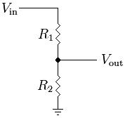
What I was getting at with the sensor setup was based on this setup:
Where Vin is +5v from the arduino, Vout is the analogue input pin and and Earth is the common ground the the vehicle/arduino share.
In the analogue input explanation on the main part of the site, it shows R1 as the 'Sensor' and R2 as a 10k resistor (i think its 10k) but what I was getting at is my sensor screws into ground, so would it still work if I was to put a 10k Resistor in R1 and my Sensor in R2 instead. I used calculations on the wikipedia page and I think it would work, but as I say while I understand some electronics, sometimes I am a little in the dark with what a microcontroller can read! But I am Learning!
If it is the case where I can swap my sensor from R1 to R2 instead will be perfect as all the sensors are attached to ground and have a single connection wire going to the dashboard where the arduino will be mounted.
If this doesnt work is why I enquired about the idea of the optoisolator design or maybe something else I dont know about?
Bugsy_malone_666:
What I was getting at with the sensor setup was based on this setup:
Yes, that setup should work. However, 10K is probably too high a value to use for R1, assuming the sensors were feeding analog dials directly. You should choose the value of the resistor to be equal to the sensor resistance around the middle of its range.
Since automotive environments are electrically noisy, it might be better to use a separate +5v supply from a LM7805 regulator to power the sensors, and connect a 10K resistor in series with the Arduino analog input.
Generally sensor inputs such as manifold air temp, coolant temp, oil pressure etc have inputs that look like the following image
The choice of R2, but especially Rin is determined by the sensors range of resistance, linearity, and the following stage which will measure the voltage.
Blimey thats a bit more of a circuit than I imagined for this type of thing! Thanks for the input I need to probably make about 3 of those minimum as I have a few starting sensors.
So basically my temperature range on gauge is normally 50-130c, in the case of digital I can probably start from 0c(or maybe less!) for a change, for the purpose of this design I need to work out roughly the resistance of 65c and work out what combined resistance would make approx 2.5v output to the arduino input? lets pretend my temp sensor on the engine has a 65c resistance of about 2k ohms, at 20c its 5k ohms and at 0c it has about 10k resistance (or something along these lines) what relation does R2/R3 have to this resistance?
At this stage I am a little confused although I can see theres alot more too it, however once its worked out, it can be applied to all analogue vehicle sensors I am likely to use. luckily for the 'weather station' part of my module (I decided to display the vehicle status while driving + outside air temp like modern cars, then when its off it can display the weather outside) I am going to look into digital sensors as they look a little easier to wire in.
Then I just need to work out how I am going to code it all.
Bugsy_malone_666:
So basically my temperature range on gauge is normally 50-130c, in the case of digital I can probably start from 0c(or maybe less!) for a change, for the purpose of this design I need to work out roughly the resistance of 65c and work out what combined resistance would make approx 2.5v output to the arduino input? lets pretend my temp sensor on the engine has a 65c resistance of about 2k ohms, at 20c its 5k ohms and at 0c it has about 10k resistance (or something along these lines) what relation does R2/R3 have to this resistance?
Generally temp sensors go the other way around - and they aren't linear - as an example GM temp sensors (which are very common on all sorts of vehicles) have the following rough R vs Temp
Deg C
Resistance
-18
25k
-7
13.5k
4
7.5k
21
3.5k
40
1.7k
70
480
100
190
The way I generally go about sizing R2 is to look at the highest value I want to read - lets say its -20 deg which will be about 28k or so. I'll use a pull up of 1/10th that or less; the value of 2.2k in the figure is what I generally use for a GM temp sensor. Rin should generally be at least 5 times that or say 10k minimum, but I tend to use the value for which I want it to start being reasonably accurate lets say 20 deg and multiply by 10 so that gets me around 33k. Then I look at the impedance requirements of the following stage - in this case the ADC and look at what is recommended in terms of supply impedance. If the output of my circuit isn't good enough to drive the ADC I would buffer the output with an opamp setup as a voltage follower (positive amp with gain of 1). If you are using a GM sensor you can probably get away with using the above circuit with the values mentioned directly. My advice would be to either find datasheets for the sensors you want to measure or to take some careful measurements while the sensors are on the vehicle to determine their range.
Blimey thats a bit more of a circuit than I imagined for this type of thing!
Its two resistors, two diodes, and a capacitor. In bulk, you're looking at 10 cents a sensor.
What I meant was rather than just a single wire connecting straight into the board and being able to be read as resistance to earth you ad 5 components per sensor, so if I used all the analogue ports, theres 25 extra components to get just 5 sensors to work and if I started multiplexing for more sensors suddenly its a world full of components just to get a few readings.
From someone who is new to more complex electronics, you soon realise how some things can have such large amounts of components in to even do a simple job!
Bugsy_malone_666:
So basically my temperature range on gauge is normally 50-130c, in the case of digital I can probably start from 0c(or maybe less!) for a change, for the purpose of this design I need to work out roughly the resistance of 65c and work out what combined resistance would make approx 2.5v output to the arduino input? lets pretend my temp sensor on the engine has a 65c resistance of about 2k ohms, at 20c its 5k ohms and at 0c it has about 10k resistance (or something along these lines) what relation does R2/R3 have to this resistance?
Generally temp sensors go the other way around - and they aren't linear - as an example GM temp sensors (which are very common on all sorts of vehicles) have the following rough R vs Temp
Deg C
Resistance
-18
25k
-7
13.5k
4
7.5k
21
3.5k
40
1.7k
70
480
100
190
The way I generally go about sizing R2 is to look at the highest value I want to read - lets say its -20 deg which will be about 28k or so. I'll use a pull up of 1/10th that or less; the value of 2.2k in the figure is what I generally use for a GM temp sensor. Rin should generally be at least 5 times that or say 10k minimum, but I tend to use the value for which I want it to start being reasonably accurate lets say 20 deg and multiply by 10 so that gets me around 33k. Then I look at the impedance requirements of the following stage - in this case the ADC and look at what is recommended in terms of supply impedance. If the output of my circuit isn't good enough to drive the ADC I would buffer the output with an opamp setup as a voltage follower (positive amp with gain of 1). If you are using a GM sensor you can probably get away with using the above circuit with the values mentioned directly. My advice would be to either find datasheets for the sensors you want to measure or to take some careful measurements while the sensors are on the vehicle to determine their range.
Ok this makes a bit of sense, I will try to get value for my sensors (made by VDO on a VW) alternatively I would have to take the sensors our and use some hot water/ice with the sensor (and pyrometer to tell me what I am reading) on to try and get an idea of temperature, that way I can get some readings to work from quickly without having to spend about 15 minutes getting the vehicle up to temp.
I can definitely see that the 'weather station' part of this project will be easier as I will be using standard components/digital ones for that. Something that I can get values for easier!
Thank you. You've just warned me of some potential complications to my plans for using an Arduino.
With regard to the varying resistance values of automotive temperature sender units, would it be possible to glue a thermistor on in the area you want to test, and then use the values from those to calibrate the Arduino to the more durable automotive senders?
Sorry if this is a dumb idea. I'm completely new to all of this, I can solder and use a multimeter, the rest I'll have to learn.
Because most automotive temp. sender units are NON lineair we have 2 options to connect sender to a micro (arduino, etc... )
First you have to map the values of the sender you wish to use.(see GM values as a nice example)
a) look for them up on the net.
b) measure the values of your sender at different temperatures.
c) Use your temperature gauge at 13.8V and pot resistor ( 5K ) to ground.
Depending on how accurate you wish to work ( most older cars normally have a 3-5% variation from correct value )
P.S. Nobody really cares about values below 40 degr. Celcius
a) record ADC value per degrees Celcius ( or F) with high and low bounderies
Create a lookup table for these values , it's a lot of work, but the most accurate, it uses a lot of valuable memory space ( these days not so important anymore )
b) dot the mapping values on a piece of Graph paper . from 40 to 120 degrees C . cut the graph up in say, 4 straight lines.
You now have for lineair lines to work from ---> 4 formulas , Guess you can work it out from here.
Im a real novice so excuse my question if it has already been addressed.
I would like to do the same thing, create an Arduino project with an LCD for my vehicle that will read several of the existing sensors.
However, is it possible to read the vehicle's stick sensors without upsetting the signal or readings on those sensors?
The sensors I want to tap into are connected to the ECU or to other devices such as gauges or cold start injectors.
I dont want any of the signals changed.
Is it better to install new dedicated sensors?