Hi cleaver people of the forum.
I want to get a PCB made but all chemicals are processes to etch a board with laser printer and acid is a bit much for me. I have access to a laser cutter/engraver. so i was thinking if i could get someone to help me design it i can get it made pretty easily.
All we need to do is get it in a format that the laser machine reads. Ive done other stuff with it before. basically it just prints from Corel. Its in scale and it is set up as a printer via USB.
As for holes and what not, In the drawing, RED lines are for CUTTING and BLACK is for ENGRAVING. Engraving will remove the copper top off the board.
now, the hard part, i dont have a schematic. ive looked at eagle and its pretty hard. i could draw it on paper and scan and attach it so you can recommend what to do.
now, the hard part, i dont have a schematic...i could draw it on paper
If you don't have a schematic, how can you draw it on paper? Sounds like you DO have a schematic, but that it is not in CAD form.
Eagle has a steep learning curve, but it isn't a long learning process. I got my first board designed and made in two days. The terminology was the hardest part.
Engraving will remove the copper top off the board.
You will need an above-average laser cutter for that.
I have seen articles about this being done before (Laser Etched PCB Production | Hackaday). They spray-painted the coper with flat black paint to make it a better surface for laser etching.
Thanks, it's good to know. I did not see any of the laser-cutting houses (pololu etc) offering laser cutting/engraving for copper-clad boards though. I guess one would need to do that at home, with their own laser cutter. Beside the novelty factor, I am wondering if it is cost effective.
You will need an above-average laser cutter for that.
well ive seen this engraver in action. It mainly used for engraving stainless tags for electrical cables for mining companies. Its pretty big. costs bout $20000 for one, so not really economical for someone just to buy. but i know them through my job. Im actually the one who set it up for them originally. its pretty cool. im sure it wont have any issues cutting a thin layer of copper.
i dont have a schematic, ive got my working prototype. its just very messy and i want to tidy it up a bit. Ill post a photo of it and draw the schematic up tonight. im at work at the moment, so itll be a few hours.
If you have the power cranked up to etch through the copper then wont it cut through the PCB as it breaks through the copper?
Well, its sensitive enough to burn away 1 layer of paper. if you glue 3 or 4 different coloured pages together and design something on the computer it can take away one 2 3 or cut through all of them. the end effect is cool. anyway, point is, i think it will be ok. will find out when i try i suppose.
There`s a g-code plug for Eagle I think, but it would have to be a high power laser to remove the copper, the way this is usually done is by milling the copper away.
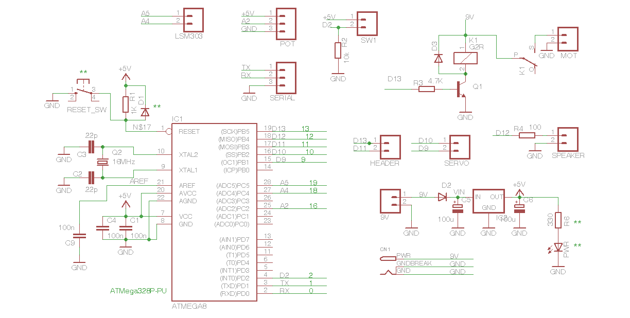
That would be easy to draw up in eagle, you have a bare minimum with a couple of components.
How much of the peripheral components get mounted on the board?
pot (needs to be accessible from outside an enclosure, so maybe attached, maybe not?)
2x switch (needs to be accessible from outside an enclosure, so maybe attached, maybe not?)
relay
the LSM303 need to be far away from the motor as it interferes. so not on the board.
i will need to use a different relay, the one i have is archaic and shit (suggestions?). the switches can be any momentary on push buttons.
im not 100% that my transistor set up is the best. It takes the relay to ground when the pin is HIGH. Ive used a BC548 to do it. But, it was my last one, and i stupidly hooked up the power backwards, now the smoke has fallen out. i have a more BC558 but i dont think they will work.
Cool,
is there some sort of scale? in mm.
can it be viewed, just the board? i think ill try get it cut in cardboard or plastic. something cheep to see if it all lines up before i do it on pcb material.
i want to have it powered by from a car battery, 12v. which the 7805 will be ok fro 5v, but the dc motor is 9v. so just need to add that in and send power to the motor.