Hay all,
I need to interface 3 2.3" 7-seg displays to the Arduino. I'd like to use something like the MAX72xx but the forward voltage of the segments is 9v @ 20mA.
I have been looking around but as yet not found anything that would work. Would it be possible to connect transistors (MOSFET or NPN?) to the MAX72xx to provide the higher voltage needed? Or am I missing the perfect replacement somewhere!
Cheers!
Assuming the LEDs are commom anode any driver/darlington type chip will work you just have to raise the voltage they are driven with.
As you say those LEDs have about 9v forward voltage so if you run them from say 12v things should work fine.
If you have a look at my speedo project http://www.robgray.com/grayit/embedded/current/speedo/schem/index.php and check out the schematic you'll see that I'm using TPIC68595 high-current shift regs and the LED's anodes are connected to the pre-regulator (battery) voltage which is a nominal 12v.
At 20mA the high-current drivers probably aren't really required but it seemed like a good idea at the time.
I love the ULN2803A chips... There are 8 transistors per chip, so you could power a 7 segment with a decimal with one chip and your controller. Keep in mynd the ULN2803A is only an array of transistors, and that you need to use another chip to actually send the signals. You would need 420mA to power 21 segments, so a 1A power brick (REGULATED!!!) would be more than enough...
This solution ONLY works if the displays are common ANODE (One posotive, and seven negatives, one for each segment.)!
Thanks, annoyingly mine are common cathode (sorry should have said). I'll look into other options as well, using these ideas as starting points. But if anyone else knows a solutions I would be more then happy to hear!
If I were to use a MAX72xx, could I use some form of transistor on the output to shift the voltage level? Or alternatively, is there another library for Arduino that would enable multiplexing from the board itself?
Well, you CAN do that, but I think Shift Registers are easier. You can use 21 NPN transistors to power the segments from the shift registers... You can probably find something like the ULN2803A, but they show ALL pins. I will also look for these! Basically you needs at least 21 NPN transistors...
How about this then?
![]()
It inverts the logic but that doesn't matter. Off the top of my head mind, I haven't tried it but it should work, write high from Arduino and the 2803 shorts across the segment thus turning it off. Write low and 2803 turns off and the segment lights via the resistor.
is there another library for Arduino
Library or not you still have to handle the hardware. Anyway the multiplexing is easy once you get your head around it.
Actually why bother, just use three TPIC68595s (high-current version of the 595 SR) and don't mux, three pins, three chips and you're done, or are you short of board space (unlikely with those huge displays).
That is the idea I was just fleshing out Graynomad! I was just trying to figure out any reason why it wouldn't work.
Previously had thought of using individual darlingtons:
(Ignore that they are the wrong displays and that I haven't put any resistors in place and they are the wrong model of transistor, this was just to get an overview of the result, not the finished product :))
"Anyway the multiplexing is easy once you get your head around it."
Don't exactly have a problem with it, just concerned with the lack of pins on the Arduino and that some are 'reserved'.
Was reading up how to bit-bang the ports and I need a full 8 bit port, but the only one available I am warned of of using as it is the TX/RX pins for programming. I have ideas in place to mix ports but it would just be easier if I could use just that one. As an aside, I am not using serial for the project, would hamper the programming of the chip if used the RX as an output?
Your post and my edit passed in hyperspace, so just on case you missed it
Actually why bother, just use three TPIC68595s (high-current version of the 595 SR) and don't mux, three pins, three chips and you're done, or are you short of board space (unlikely with those huge displays).
Solves your pin problem.
I can't find TPIC68595 on either Farnell or RS Components, am I being exceedingly dumb here? :LOL:
Oops, my bad.
TPIC6**A**595
Well it sounds almost the same :-[
Here's a data sheet
http://www.robgray.com/grayit/embedded/components/datasheets/TPIC6B595.pdf
And I just realised that I've used the
TPIC6**B**595
That looks almost the same.
Both available at Farnell and Digikey.
Sorry about that, I cut and pasted from my schematic, obviously that's wrong as well.
:lol: Graynomad
Ordered a couple of the A's. Now I just need to figure out how to get the info to them!
Cheers for your help guys!
Yes! Got one display working just to make sure that it all works and to test out coding.
- YouTube So cool to see a 7-seg display connected by only 3 wires!
Next is to figure out how to split an int into its base units. Have to get the minutes from an int var and pull out the 10's and 1's from it. Thinking cap on!
Try
tens = value / 10;
units = value % 10;
That worked!! I now have it counting from 00 to 99 
Annoyingly and stupidly, I mananged to under order the resistors so I can't do more then 2 displays at the moment. Dead chuffed that it is working as planed at the moment. Next job is to try and get it to work on the larger displays now with the different voltages.
I don't know about anybody else but I cannot view your Y-T videos as they are labeled as 'private'.
Ooops meant to put them up simply as unlisted [smiley=embarassed.gif] not private. Changed now!
BTW they aren't anything exciting, I am just a little proud that with the help of these guys that it actually works. Normally I have a great idea then can't figure out how to make it function!
I am hoping to find a way of making a library to make it easier to display using shift-reg's as I am not aware of one. Plus makes it easier it implement on any future projects I may have.
Okay so have everything wired up and it is working - sort of.
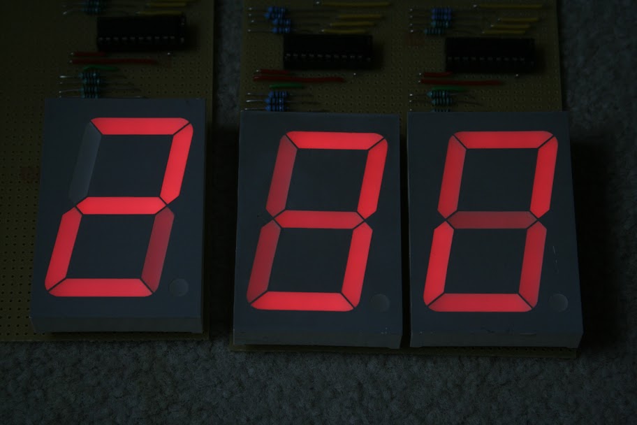
I seem to be getting a 'shadowing' across the displays. The following should be displaying 230:
And it is, however it also seems to be showing the previous digits as well. The camera doesn't pick up the light differences too well. You can see that there is a 230 displayed as they are brighter. The remaining LEDs are at about 25-50% brightness.
As far as I can figure this is an issue with the way that I am using the shift registers with a common cathode display, as suggested by Graynomad. I can't use the G line to blank the display while updating (if G goes high to blank the display all the outputs switch off thus actually turning on all the LEDs), so you are seeing the effect of the other numbers being pushed down the shift registers.
The only other way I can think of is to cut power to the GND of the displays as the screen updates using a transistor. I was hoping though that someone else may have an alternative solution that could be applied in software.
For those interested here is a picture of the minute board:
Solved the ghost problem. Have put a transistor into the ground line for the displays. Now the Adruino can turn off the displays while it updates. Only downside is a reduction in brightness. Have to wait until tomorrow to see how that affects the readability in daylight.