I am fairly new to using the RGB LED matrix and I am stuck trying to understand what type of LED drivers can be used to control this specific RGB LED matrix LED Matrix - Tri Color - Large - COM-00683 - SparkFun Electronics. My end goal here is to create my own common cathode led matrix controlled by small prototype PCB board, so the smaller the chip is , and/or the less number of chips needed the better.
What I currently have is arduino UNO board running with atmega328P to program the LED matrix with.
Assuming the individual LEDs take 20 mA you will need a driver capable of sinking 20n3 mA where 'n' is the number of anodes per cathode. A transistor per cathode should do the trick. For the anodes you just need current limiting resistors.
I don't think that's the right hardware solution.
What you need is 3 MAX7219. Each will have its Segment drivers connected to one color of anodes.
Each will need diodes between its digit drivers and the common cathodes.
Diode Anodes will connect to the matrix pins in parallel, and the cathode to the Digit pins.
This will take advantage of the MAX7219 shutdown mode:
"When the MAX7219 is in shutdown mode, the scan oscillator is halted, all segment current sources are pulled to
ground, and all digit drivers are pulled to V+, thereby blanking the display. "
Then write a sketch that alternately takes each one out of shutdown mode 1/3 of the time.
Control the 7219s with SPI, giving each its own slave select line for easier software creation.
I am familiar with those MAX7219 , and I was wondering was there one led driver that could power an 8x8 RGB led matrix, or is my only option getting multiple MAX7219's?
The thing is I am trying to eventually create a LED RGB matrix thats 16x16 , so how many MAX7219's would I need for that? I mean instead of creating one 16x16 RGB Led matrix, would it be more efficient to daisy chain 4 '8x8' RGB led matrixs? IF so then there is no way I can create a small enough prototype board that would fit all those MAX7219's on it so that's my conundrum.
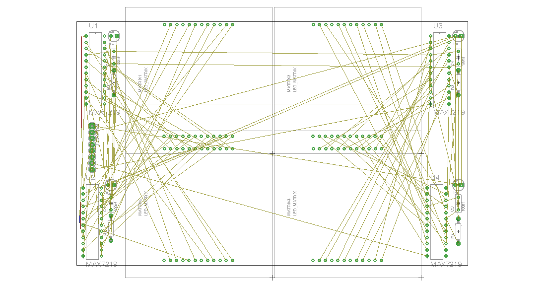
Sure you could.
Would look something like this , a just a little wider to accomodate 3x MAX7219 at each corner instead of just 1, and the diodes I mentioned, and with 8 more pins on each display.
Otherwise, you'd need like a 40-pin chip for each matrix (8 red anodes, 8 blue anodes, 8 green anodes, 8 cathodes = 32, + Vcc, Gnd, current set pin, serial data in, serial data out, clock, chip select, and 1 left over for something yet to be defined).
I suppose you could program a '1284P to do that, but you'd need current limit resistors.
I am fairly new to using the RGB LED matrix and I am stuck trying to understand what type of LED drivers can be used to control this specific RGB LED matrix LED Matrix - Tri Color - Large - COM-00683 - SparkFun Electronics. My end goal here is to create my own common cathode led matrix controlled by small prototype PCB board, so the smaller the chip is , and/or the less number of chips needed the better.
Why common cathode?
Common anode is sooooo much easier to drive using standard chips, eg. two TLC5940s will drive a common anode RGB LED matrix.
Ok that only reason I havent used the common annode version is because I keep reading on random forums that the common cathode matrix will last longer and the color variation comes out much better in comparison.
@CrossRoads Thanks for the schematic and links btw these are really helpful, and I am curious to what you about common cathode vs common anode is there a difference (aside from how to control it)
mfran89:
Ok that only reason I havent used the common annode version is because I keep reading on random forums that the common cathode matrix will last longer and the color variation comes out much better in comparison.
That makes no sense at all. The LEDs inside the matrix will be exactly the same, the only difference is the way they're connected.
Ok that only reason I havent used the common annode version is because I keep reading on random forums that the common cathode matrix will last longer and the color variation comes out much better in comparison.
Yes that sounds utter rubbish to me also. There is no reason why bonding a chip out differently would affect anything.