16x2 LCD Mystery [update]

Hey guys,

i bought a 16x2 LCD but i cant get it to work. (link to product page)
i have no datasheet/model name, and no potmeter (instead i hooked VO to ground). i am using the LiquidCrystal libary in 4bit mode.
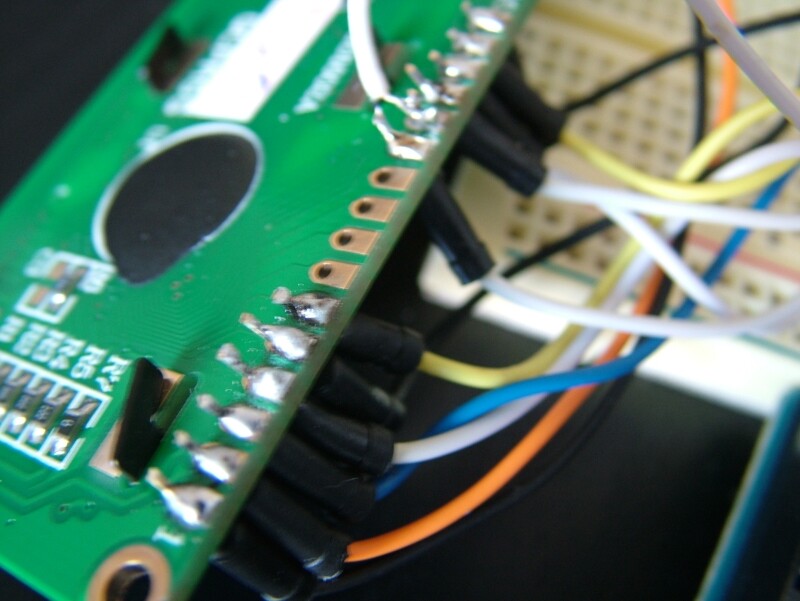
at the back of my lcd i can read some model numbers: [1602A] , [JGD1602A] , [QCPASS] (dont know if anyone else can find his datasheet, but i cant)

problem: (using the LiquidCrystal libary)
1 - lcd.setCursor causes a blank screen (whereever i place this command and with whatever arguments filled in -> lcd.setCursor(0,0) always result in blank screen even if i use any prints)
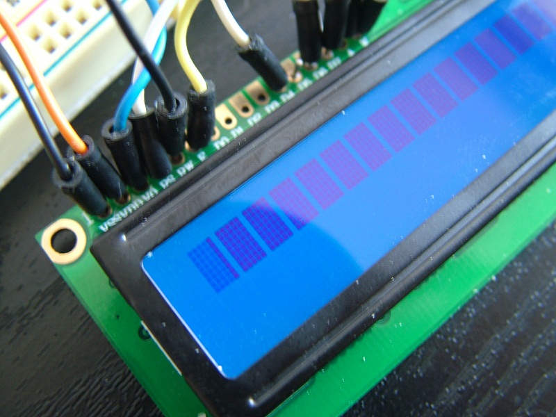
2 - with hello world example of arduino LCD example (these i mean) ..with the lcd.setCursor(0, 1) line excluded (removed),
my display shows the 1st row all black (LCD = 5x8 dots x16chars x 2 rows) and second row is all blank (removing the lcd.print() line in the loop dit not solve this..)

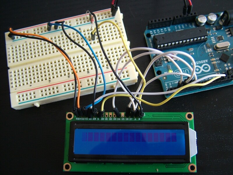
These are my connections from LCD:
1 vss - gnd
2 vcc - 5v+
3 vo - gnd
4 rs - D12 (arduino)
5 R/W - gnd
6 E - D11 (arduino)
7 data 0 -
8 data 1 -
9 data 2 -
10 data 3 -
11 data 4 - D5 (arduino)
12 data 5 - D4 (arduino)
13 data 6 - D3 (arduino)
14 data 7 - D2 (arduino)
15 A - 5v+ Through 220 Ohms
16 K - gnd

PS: furthere more i have nothing else connected to my lcd nor my arduino & Picture at product page is incorrect!

if sombody have any great ideas i appriciate it alot! (i am working on this now for more than a week!)
Nick

I think fixing the "don't have potentiometer" is your first step. Take a look at this thread. I spot a few very apparent things that will help you.

http://arduino.cc/forum/index.php/topic,102266.0.html

Picture at product page is incorrect!

Well at least we know what the display does not look like.

Don

I assume that the backlight is working and the epoxy blobs on the back of the display don't get hot. This would normally mean that your power is connected properly, there are some oddball LCD modules with the Vss and Vcc pins reversed, but don't have one of those. You may, however, have misinterpreted the pinout. If your row of 16 pins is at the upper left or lower right then pin 1 is near the outside edge of the board. If your row of 16 pins is at the lower left then we will have to do some more research.

You are seeing one row of blocks on the display. This means that your use of 0 Volts on pin 3 may be adequate although probably not optimum.

The single row of blocks also indicates that your LCD controller is not being properly initialized. Since the LiquidCrystal library along with the Hello World sketch are known to work that leaves your interconnections as the most probable cause of your problems.

While you are waiting for John and I to wake up you should post some pictures as mentioned in his link.

Don

hey, thnx for the quick replies!

I think fixing the "don't have potentiometer" is your first step. Take a look at this thread. I spot a few very apparent things that will help you.

ill try to get 1, but i also read that connecting vo to gnd would cause full brightness, soo this way i dont ned a pot?

The single row of blocks also indicates that your LCD controller is not being properly initialized. Since the LiquidCrystal library along with the Hello World sketch are known to work that leaves your interconnections as the most probable cause of your problems.

While you are waiting for John and I to wake up you should post some pictures as mentioned in his link.

see pictures with this post.. and the rest is included in the next post.

here're the other pictures,
please note: the lcd with a blank screen is the snapshot of the arduino with the complete example, the lcd snapshot with 1st row black is the moment when the lcd.setcursor(0, 1); is removed from the sketch.

Post your code!
Don't forget to use the code tags.

We need a photograph that allows us to unambiguously follow the six wires that connect between your LCD module and your Arduino. Your second photo is the closest but using wires of the same color on adjacent pins doesn't help things.

You should also redo the solder connections on your LCD module. You have used too much solder so go easy next time. If you can find a header strip that might be a better choice for tinkering.

I am concerned about the first four columns of dots in your first block. They shouldn't be lighter than the rest.

You shouldn't have to change the sketch but you could try commenting out everything inside loop() if you think it might help.

I never saw an LCD module with the pins identified as yours are. That's a really good idea and I'm surprised that they spent the extra money to do so since that is the only silk screen work on that side of the board.

Don

sketch for 1st row black:

// include the library code:
#include <LiquidCrystal.h>

// initialize the library with the numbers of the interface pins
LiquidCrystal lcd(12, 11, 5, 4, 3, 2);

void setup() {
  // set up the LCD's number of columns and rows: 
  lcd.begin(16, 2);
  // Print a message to the LCD.
  lcd.print("hello, world!");
}

void loop() {
  // set the cursor to column 0, line 1
  // (note: line 1 is the second row, since counting begins with 0):
  //lcd.setCursor(0, 1);
  // print the number of seconds since reset:
  //lcd.print(millis()/1000);
}

sketch for blank screen:

// include the library code:
#include <LiquidCrystal.h>

// initialize the library with the numbers of the interface pins
LiquidCrystal lcd(12, 11, 5, 4, 3, 2);

void setup() {
  // set up the LCD's number of columns and rows: 
  lcd.begin(16, 2);
  // Print a message to the LCD.
  lcd.print("hello, world!");
}

void loop() {
  // set the cursor to column 0, line 1
  // (note: line 1 is the second row, since counting begins with 0):
  lcd.setCursor(0, 1);
  // print the number of seconds since reset:
  lcd.print(millis()/1000);
}

We need a photograph that allows us to unambiguously follow the six wires that connect between your LCD module and your Arduino. Your second photo is the closest but using wires of the same color on adjacent pins doesn't help things.

any suggestions how i can fotograph any bether pictures? i can assure you that my connections are the same as my first post..

You should also redo the solder connections on your LCD module. You have used too much solder so go easy next time. If you can find a header strip that might be a better choice for tinkering.

well, im keep getting better each time. but does it make the situation any bether by resoldering all pins (i dont know if i can desolder that good already, so it might get even worse..)

I am concerned about the first four columns of dots in your first block. They shouldn't be lighter than the rest.

Right before posting the pictures it did not apear this way, maybe i fried them somehow? but anyway the 1st row have been all black even whitout this error. (so this does not cause the problems)

You shouldn't have to change the sketch but you could try commenting out everything inside loop() if you think it might help.

okey, ill do that instead.. :3

I never saw an LCD module with the pins identified as yours are.

how came? if i search 16x2 lcd display on google i can find lots of the same pin-outs..

That's a really good idea and I'm surprised that they spent the extra money to do so since that is the only silk screen work on that side of the board.

about what idea are you talking about? extra money spend at what??

thanks nick

any suggestions how i can fotograph any bether pictures?

We have to be able to follow each wire without being confused as to which one we are following.

i can assure you that my connections are the same as my first post..

That is the problem. Your connections didn't work then, and they still don't work.

but does it make the situation any bether by resoldering all pins

Yes, if the original connections were bad. With such a big solder blob we can't see if there is a 'cold' connection underneath.

about what idea are you talking about?

I am talking about the fact that each pin is labeled for it's function. Usually they just identify pin 1 and/or 16 as they do on the other side of your board.

extra money spend at what??

The white lettering is done with a silk screen (like a stencil). The application of this lettering involves an extra manufacturing step. It doesn't cost anything extra to add this lettering if you are already using a silk screen for other information, but that isn't the case here.


You have a problem that is most likely related to one or more of the six connections between your Arduino and your LCD module. Your problem could be one or more wires in the wrong place, it could be one or more bad connections, or it could be a combination of the two. You should consider removing all the wires and starting over, possibly following the Lady Ada tutorial that is mentioned in the link given in reply #1. You did look at that link I hope.

Don

I am concerned about the first four columns of dots in your first block. They shouldn't be lighter than the rest.

Right before posting the pictures it did not apear this way, maybe i fried them somehow? but anyway the 1st row have been all black even whitout this error. (so this does not cause the problems)

Try putting some pressure on the black trim that surrounds your LCD glass and see if this condition changes. You could have a loose connection between the LCD display and it's pc board.

Don

Try putting some pressure on the black trim that surrounds your LCD glass and see if this condition changes. You could have a loose connection between the LCD display and it's pc board.

well look at that! it sure did change the condions.. by slightly give some pressure on the frame it has been solved, how would i get this pressure on the frame forever? or do i always have to live with the fact that its broken?

You have a problem that is most likely related to one or more of the six connections between your Arduino and your LCD module.

i was almost 100% sure that i connected everything according to the connections mentiond on my 1st post, do you realy think my problem is that i have hooked up something wrongly?

anyway ill desollder everything and resolder everything with a little less solder on each pin. im still not realy good at soldering but ill try (any tips are welcome)
i will let you know when im done and what the results are.

...You did look at that link I hope.

hehe, i found that page long before posting this problem trough google and read it many times already..

how would i get this pressure on the frame forever?

By twisting the black tabs that are extending through the pc board. You can see five of them in photo DSCF5870.

Don

i'd like to inform you that i just bought a 10k potmeter. i tryed but no big results:

this sketch,

// include the library code:
#include <LiquidCrystal.h>

// initialize the library with the numbers of the interface pins
LiquidCrystal lcd(12, 11, 5, 4, 3, 2);

void setup() {
  // set up the LCD's number of columns and rows: 
  lcd.begin(16, 2);
  // Print a message to the LCD.
  lcd.print("hello, world!");
}

void loop() {
  // set the cursor to column 0, line 1
  // (note: line 1 is the second row, since counting begins with 0):
  lcd.setCursor(0, 1);
  // print the number of seconds since reset:
  lcd.print(millis()/1000);
}

witch caused me a full blank screen, is now causing to show about the last 4 or 5 collums black when i turn the potentiometer at a specific moment (i couldn't see them before because i wasn't able to ajust brightness)
i can see them just for a very short time about 50 mil seconds and than they dissapear, wich lets me thinking that the lcd.setCursor(); caused somekind of refresh or reset on the lcd's chip.

questions:

  1. could it be that this lcd is not Hitachi HD44780 Compatible?
  2. how does non-Hitachi HD44780 LCD's react to this libary?
    nick

... is now causing to show about the last 4 or 5 collums black when i turn the potentiometer ...

You very well may have a defective LCD.

could it be that this lcd is not Hitachi HD44780 Compatible?

It is not likely.

how does non-Hitachi HD44780 LCD's react to this libary?

They typically work properly

Once again I will recommend that you disconnect all of your wires and start again and carefully follow the tutorial at Arduino Tutorial - connecting a parallel LCD.

Before you get to the point where you connect the six wires between the LCD and the Arduino you should see a single row of boxes on the top line of your display (the LCD in the tutorial is upside down). If you don't get that display then there is no sense going any further.

Don

Once again I will recommend that you disconnect all of your wires and start again and carefully follow the tutorial at Arduino Tutorial - connecting a parallel LCD.

okey i read that, disconnected everything and when i connect pin15 to 5v (through 220 ohm) and 16 to ground it basicly does nothing, there is no light in there.
the tutorial u send me wich shows an lcd under same connections wich does light up..

does this mean i will have to contact my seller because of a defect? or did i burned it myself?

nick

does this mean i will have to contact my seller because of a defect? or did i burned it myself?

The backlight seems to have been working in the pictures you posted in reply #4 - so what do you think?

Don

when i reconect everything i have my backlight back and can see the first row of black collums just like in picture.
when i reconnect everything like post 1 and disconnect the data lines between lcd-arduino, the lcd just shuts down completly
but the strange thing is: when data line 4 (D4 lcd) is connected to the apropiate pin on the arduino (digital 5) -> the lcd is back /online / the circuit somehow is complete agian and i see backlight with collums just like the picture posted before.

and when i disconnect vdd (5+) pin or pin 15 (pin A), only the backlight goes down, i can still see the collums bieng black (1.st row) (note: everything else is conected)

but the strange thing is: when data line 4 (D4 lcd) is connected to the apropiate pin on the arduino (digital 5) -> the lcd is back /online / the circuit somehow is complete agian and i see backlight with collums just like the picture posted before.

This strongly suggests a wiring error. This puts us back almost a week to the post that said: "We need a photograph that allows us to unambiguously follow the six wires that connect between your LCD module and your Arduino."

Don