I need to see if this schematic is correct to use an Atmel 644p standalone with the Arduino IDE. I have went over several schematics with a MAX232 but, some have resistors between the USB jack and MAX232. None of them explained why they are needed.
Any advice and constructive criticism is welcome.
Thanks!
I think you are terrible mistaken in your proposed use of a MAX232 type RS-232 to TTL voltage converter chip to use as a USB type serial converter chip like a FTDI FT232RL. The USB connections to a PC can only be used with a chip that can enumerate and function as a USB device, which a simple voltage translator chip like a MAX232 is most certainly not.
Lefty
Caps on MAX232 are not correct.
Should be 5 total - you only have 3.
MAX232 does not do USB to Serial - you need a part like FT232RL for that. See www.ftdichip.com
I would suggest a module like MIKROE483 from mouser.com $11
Also FTDI Basic or FTDI Breakout board
Or CP2102 module from e-bay, use the BATI kind that have DTR available at a breakout hole.
MAX232 will output +/-10V signals, and expects the same back. As drawn, T2out will blow up the Rx pin. And R2out will likely damage a PC if connectedl.
Put a diode across the reset resistor - anode to Reset, cathode to +5v.
What does cap C9 connect to when the jumper is closed?
C4 should be bigger, like 1 or 10uF.
C8 can be 1uF.
Add 0.1uF caps to the VCC, AVCC, AREF pins, as close to the pins as possible.
Can draw the VCC/AVCC parts next to C5.
JP5 - RTS should be DTR, I imagine you want it going to C9.
Check the order of the pins, make sure an FTDI Basic, or FTDI cable can plug straight on. I always double check against the ProMini schematic to be sure.
Wow, ok, learn something new everyday..
Attached is an updated schematic.
Thanks Crossroads
Flip over diode D1. The intent is for any spikes/etc. on the reset line to get bypassed into the Vcc line.
Planning to connect some external parts to this? I would add another header or other means to connect +5, Gnd to off board devices.
The FTDI and AVR header can be used as well.
CrossRoads:
Flip over diode D1. The intent is for any spikes/etc. on the reset line to get bypassed into the Vcc line.
Oh, ok... Must have misinterpreted what you wrote...
Planning to connect some external parts to this? I would add another header or other means to connect +5, Gnd to off board devices.
The FTDI and AVR header can be used as well.
Yes, I wanted to get the basics first. This board is to experiment to see how the 644 will do in a bigger project. Wanting to learn more about standalone micros before I make any PCBs for the larger project.
Thanks for your help CrossRoads.
Well, you could always 'hack' your Uno 
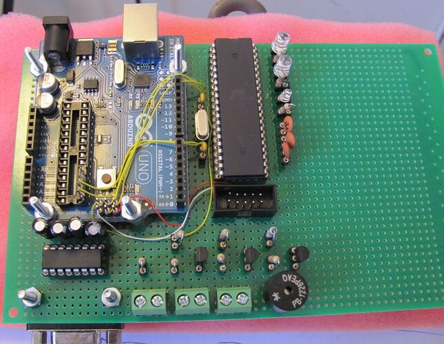
Here's one of the early things I did with arduino, adapting an Uno to work with a '644P.
The larger memory and dual serial ports were needed.


