I'm running a partial test circuit right now and while thinking about voltage differences, I realized I may need a level converter. But then I wondered ... the circuit is working as expected now, so is the converter necessary?
Basically I have an Atmel that's currently running at 5V, sending MOSI and CHK to a LED string that's running at 3.3V. As I said, it's working as expected. But, shouldn't I need a level converter on the MOSI and CHK lines because of the voltage difference?
What if the voltage was opposite, with the Atmel running at 3.3V and the LED string at 5V. Keep in mind, the only thing connecting the LED string to the Atmel are the MOSI and CHK lines. The strings share a common ground with the Atmel, however they have separate power sources in either instance.
So, level converter, yes, no? And if yes, any suggestions for one? I don't want a completed package like SFE's product as this will be built into a new design.
Depending on how fast you are running your SPI communications, a simple potential divider will do the trick.
As for the other way around, it "may" work, if the 3.3v given out by the Atmel is within the Vih specification of the input to the LED controller chip - it will be specified in the data sheet. If not, then yes you will need some way of increasing the voltage. There are many options around, and many schematics and tutorials online.
Yeah, I would just need to go from the Atmel, running at 3.3V, sending CHK and MOSI to the LED driver which runs at 5V. The logic voltage on the driver is, at its minimum, 0.8 x VCC, and at its max, VCC. So that means for a "high" to be registered, it has to be between 4V and 5V. (A "low" is registered between 0V and 1V.)
So I would need to go from low to high for those two signals. There's nothing coming back TO the Atmel.
There's two questions I have in this level converter topic:
High -> Low
Depending on how fast you are running your SPI communications, a simple potential divider will do the trick.
Do real resistors behave so bad, compared to ideal resistors without any frequency dependency, and compared to diodes I see usually as level converter recommendation ???
Low -> High , if I do not want to rely on the assumption that 3V is high enough to be a logic HIGH in the 5V area ( KirAsh4's issue )
Do I need some IC doing the level shift, or minimally 2 transistors to get it non-inverting, or is there another electronics trick to "amplify" a 0...3V signal I'm not aware of ???
michael_x:
There's two questions I have in this level converter topic:
High -> Low
Depending on how fast you are running your SPI communications, a simple potential divider will do the trick.
Do real resistors behave so bad, compared to ideal resistors without any frequency dependency, and compared to diodes I see usually as level converter recommendation ???
Yes, they can cause problems with high frequency comms - remember, traces have inductance - inductance + resistance = filter. Yes, you could use a diode to drop a small amount of voltage (schottky = ~0.4V, silicon = ~0.7V) so with a silicon you'd go from 5V to 4.3V - a chain of them together could get you to (2silicon + 1schottky) ~3.2V, but remember that the diodes block current in the reverse direction, so won't be able to sink current - you'll need a pull-down resistor to provide the logic low level. Cheaper and simpler to just use 2 resistors. Or you can use transistors to act as proxy switches, or a chip that can accept a 5V logic signal and give out a 3.3V one for higher frequency communications. There's (as always) many options.
michael_x:
2. Low -> High , if I do not want to rely on the assumption that 3V is high enough to be a logic HIGH in the 5V area ( KirAsh4's issue )
Do I need some IC doing the level shift, or minimally 2 transistors to get it non-inverting, or is there another electronics trick to "amplify" a 0...3V signal I'm not aware of ???
The simplest thing is to use any readily available 74HCT part that can be adapted to a buffer. One of the most common is the 74HCT08 quad AND gate. Take one of the AND gates, tie both inputs together, and it becomes a simple buffer - what logic level you put on the input is presented on the output. Run the chip from 5V, and the output will be a 5V logic level output. Being a TTL level chip (the T of HCT), the input "high" level is only 2V, so can be driven happily by the 3.3V of the Atmel.
It's not the resistors that have the inductance, but the tracks on the PCB. They have a "characteristic impedance" - the resistors couple with that to make a low-pass filter.
It's only a problem at incredibly high frequencies, which is why you see high frequency comms traces on PCBs with wiggles in them to keep the length, and hence the impedance, the same.
However, even relatively low digital frequencies have some very high analogue harmonics - so the normal effect is of a "rounding" of the nice clean square wave rather than a blocking of it completely. This can cause timing issues at high communication speeds, where one signal might not have completely risen to the right level before another (say a clock signal) has reached that required level, so the receiver gets spurious values.
but now it's completely unclear to me how a pullup + reverse biased diode is any better than 2 resistors, if they are wired on similar pcb trace lengths...
With the diode you don't have the resistance in with the trace, but just pulling up to Vcc. With the potential divider you have two resistors - one pulling down to ground, and one in series with the signal. So, with the diode, there is less filtering effect.
So is it worth looking for a single IC that would do the level translation for 2 or 4 channels, or just use a few resistors and an n-channel like SFE's level converter does? I just need the transmit lines, not RX as there won't be anything coming back.
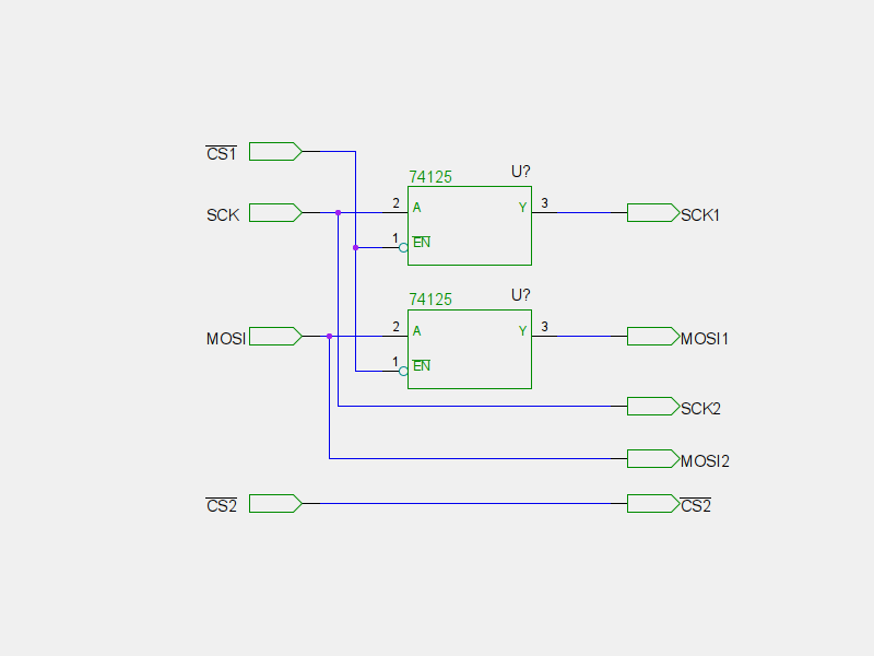
However, this brings up another question, if I have another SPI device that requires 3.3V logic levels, can I have those signals tapped BEFORE the level converter? Basically, something like this:
The 5V device does not have a slave select pin, but the 3.3V one does. So if I just send data down the MOSI line it should still work to trigger the 5V device with CHK, but the 3.3V device won't do anything till I actually select it. Yes? But then what happens with the 5V device since it will still see the data being sent to the 3.3V device ...
Or should I enable the USART in SPI mode and run the 5V device from that with everything else off of the SPI port? Not that I have any clue how to get that accomplished but then anything can be learned, right?
For this application you will be best off using a 74HCT tri-state buffer chip. That way you can have a chip-select to gate the SPI signals to the 5V chip only when you need them.
Something like the 74HCT125.
And yes, tap the 3.3V signals off before they go into the 74HCT125 chip.
Thanks majenko. That will certainly come in handy. For now though, I've decided to make the design modular. The 5V SPI device will be an add-on with its own controller, which then communicates via I2C to the main controller. This'll allow me to focus on getting the initial stage of the project done, and add other stuff later.
So this just left me with a single issue still needing to be addressed, which is converting the 3.3V signal from the uC to the 5V signal needed for the LED drivers. Two signal lines ... I may just use the schematic for SFE's level converter and build it into my circuit. I should work ... I think.
I'm looking at SFE's level converter schematic and figured, all I need are the TX lines, so would it be enough to just add two of these, one on the MOSI and the other on the CHK signal lines?
That circuit works well though I would make the 3V3 pull-ups 2K2 and the 5V, 4K7. A Little more current makes the bus a little more noise tolerant...
1K and 2K2 work well too. on my level translator.