I'm sending the Vout of an ACS712 20A to an ADC pin on Arduino Uno. According to it's datasheet, the Output sensitivity is 66mV/A. So what I do is multiply by 5/1024, then -2.5V and then divide by 66mV/A or 0.066V/A
When it's a resistive load, I get the same Amp value as my Tester does, but when it's an inductive load, I don't get a quality measure. I mean, with an AC motor, my tester prints 0.3A and my ACS712 ''senses'' 1.2A. What could it be? Do I have to make a special filter? I think what my ACS712 senses is some harmonics produced by the motor's inductive load.
Pin 6 and 5 the cap on them forum a filter
Application 1. The ACS712 outputs an analog signal, VOUT .
that varies linearly with the uni- or bi-directional AC or DC
primary sampled current, IP , within the range specified. CF
is recommended for noise management, with values that
depend on the application...
what if u measure the ACS' output over a second and print minimum and maximum?
the ACS should b able to show u the current with a quite high resolution (100kHz, i think)...
The reading you get from the ACS712 when measuring AC will vary throughout the cycle. You need to add together the squares of a lot of current measurements, divide by the number of measurements, and take the square root of the result. This gives you the RMS value of the current, which is how AC is measured.
To make it faster, I suggest you do the following:
-
Establish the ADC reading you get for zero current - nominally 512 but will probably be a few counts off.
-
Each time you take a reading, subtract that value, convert to signed long, then square it and add it to the running total (which can be a signed or unsigned long). Doing this in long arithmetic is faster than doing it as floating point.
-
When you have accumulated enough readings, divide by the number of readings you took. Then convert to float, take the square root, and finally do the * 5.0/(1024.0 * 0.066) calculation.
Guys, I've already put a capacitor on the Filter Pin.
When I said "filter" I was talking .filtering the Vout.
And yes, I've already done an algorithm in which I take more than 60 values on the 60Hz period (16.67 ms) and take the Maximum value of the readings.. I told you, it works for resistive loads. That Maximum value I get is already the RMS. I used a tester to prove it. The problem I get is when I'm sensing an INDUCTIVE load, like an AC Motor...
Your doing your math for DC load to use this with a motor you'll need to run it threw a R-M-S converter
what if u take 1000 samples per second?
what is the minimum?
what is the arithmetic mean of the samples of 1 second (i think that is what the DC amp meter measures)?
Firstly, what makes you think your test meter is telling the "truth"
You refer to a resistive load - is this with a DC supply or the AC supply.
If the former then using a light bulb (resistive) repeat your tests with an AC supply and see what you get after applying RMS sampling.
If there's a difference between meter and transducer then I respectfully suggest your test meter is telling porkies.
With respect to differences between resistive and inductive current, there is none, the "difference" is in the phase angle between the current flowing versus the system voltage. An amp is an amp, irrespective of what its flowing into. Its "shape" in non-DC type circuits might change but that's where RMS correction comes into play (to determine the equivalent power or heating capability)
Actually, there's a difference between current on resistive load and current on inductive load other than the phase angle. There are some non-linear devices that can make your ''Current curve'' different (Not sinusoid), so in case of nonlinearity; RMS and Peak values are useless when you talk about heating capability or DC equivalent power. Google ''True RMS''.
No-one said it was the same. You will note that I referred to the "shape" of the curve and the need to factor in RMS correction. There only is 'true-RMS' that you refer to and that is simply "RMS" as defined by the acronym Root-Mean-Square. Most simple or inexpensive meters that are supposed to measure AC voltages and current assume a sinusoidal waveform.
Or to put it another way, the test meter is designed/calibrated on the assumption that the waveform is sinusoidal whereas the motor load current will definitely not be sinusoidal due to the continuously changing inductance of the motor windings as the rotor bars pass the pole pieces. The transducer is responding to these non-linearities, as it is designed to do.
Many years ago when working on large generator synchronisation problems between remote oil platforms we could clearly see the rotor bar passing frequency superimposed onto the line frequency. This was sufficient to cause major headaches before we resolved the issue.
Well I'd not describe my mains as sinusoidal - too many SMPS's on the line:
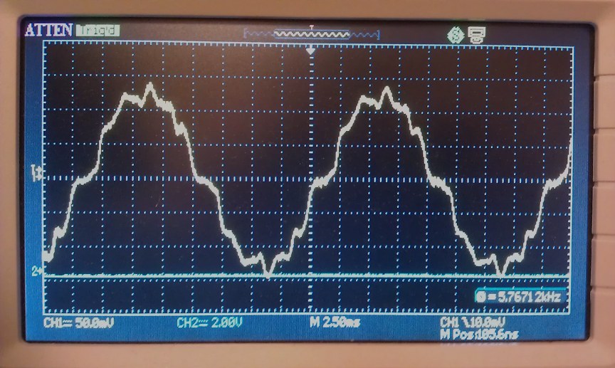
Actually its capacitive pick-up from a mains cable, so not quite accurate,
but safer than trying to rig up a resistive divider from 240V ac.
[ the current waveform is left to the imagination! ]
If you look at the ripple on the mains base frequency you will observe it is consistant at 12 times per cycle. This suggests it may well be inductive interference from a motor or poorly constructed generator and possibly illustrates the point I was making about pole passing frequency. The noise could be from a neighbours motor on the same phase from the substation as yourself. This type of problem will only get greater as air and ground source heat pumps become more popular. No doubt some of the cheaper PV invertors will also contribute.
On the subject of test meter accuracy on AC measurement. Some of these meters are so cheap there is every possibility that they use a simple rectifier and RC filter to produce the so-called RMS signal to feed the DC section of the measuring device. As such they will be calibrated for a sinusoidal waveform and any variation from that form will introduce error.
Hi
I'm working in a project using the ACS712 curent sensor ,
and i had exactly the same problem with the inductive load whene i compare it with the multimetre .
did anyone has resolved the problem
Thanks for your reply and your help
Regards Youness