Hi all,
I have a project I'd like to share and request some comments. It is a Arduino based multiprobe for limnological/oceanographical/biological purposes.
The idea is to have a submersible modular instrument to measure the penetration of light in the water column. So we need the following components:
Radiometer: a multi range radiometer for PAR (photosynthetic active radiation aka visible light, 400-700nm), UV-A (320-400nm) and UV-B (280-320nm); photodiodes (and filters if necessary) with OpAmps.
Depth sensor: to correlate other sensor values with depth; the sensor we intend to use (MS5541) comes with a temperature measurement. Measuring depth will rarely extend 30 m. Sensor comunicates via SPI and requires a clock signal (MCLK). Needs a level shifter 5V->3.3V.
Temperature: an internal measurement (DS18B20) might be useful for temperature compensation of the amplification circuit for the photodiodes.
Datalogger: all sensor data shall be logged on a µSD-Card, csv is ok.
Time stamp: DS1307 RTC.
Power supply: we need +5V for the µP, +/-5V for the OpAmps, 3.3V for the SD-Card and the depth sensor. DC-DC-Converters might be nice for higher efficiency (and the negative voltage), although I do not know if it is necessary. The battery voltage is monitored. The powerbus carries a battery voltage line.
Small size: we want to take it easily on field trips and maybe have it in the hand luggage during flights. A 0.5-L-beer can would be a nice form factor.
Pin count: ADC (radiation + battery): 3+1; µSD + depth sensor on SPI: 2 + 3; D out (MCLK, indicator LEDs): 1 + x; D in (DS18B20, measurement mode?): 1 + x; RTC: I²C.
So it actually sounds like a job for an Arduino with an ATMega 328, but up to now we have a sketch which is already around 21kB and the SPI-communication to the sensor is still missing along with all the maths for calculating the real values from the raw readings and the calibration factors. Also, it is modular, because one day we'd like to implement a conductivity probe (to measure the salinity, important in oceanography), so we might need a bigger memory and additional pins (and a conductivity sensor, any suggestions?). Another idea is to have a module to measure chlorophyll fluorescence in the water column to calculate the amount of phytoplancton. But this is really a very late step in the process.
So I thought the ATMega 644P is a nice choice, because it is not such a monster as the 2560 and, as the core of the Sanguino board, it works with the Arduino IDE.
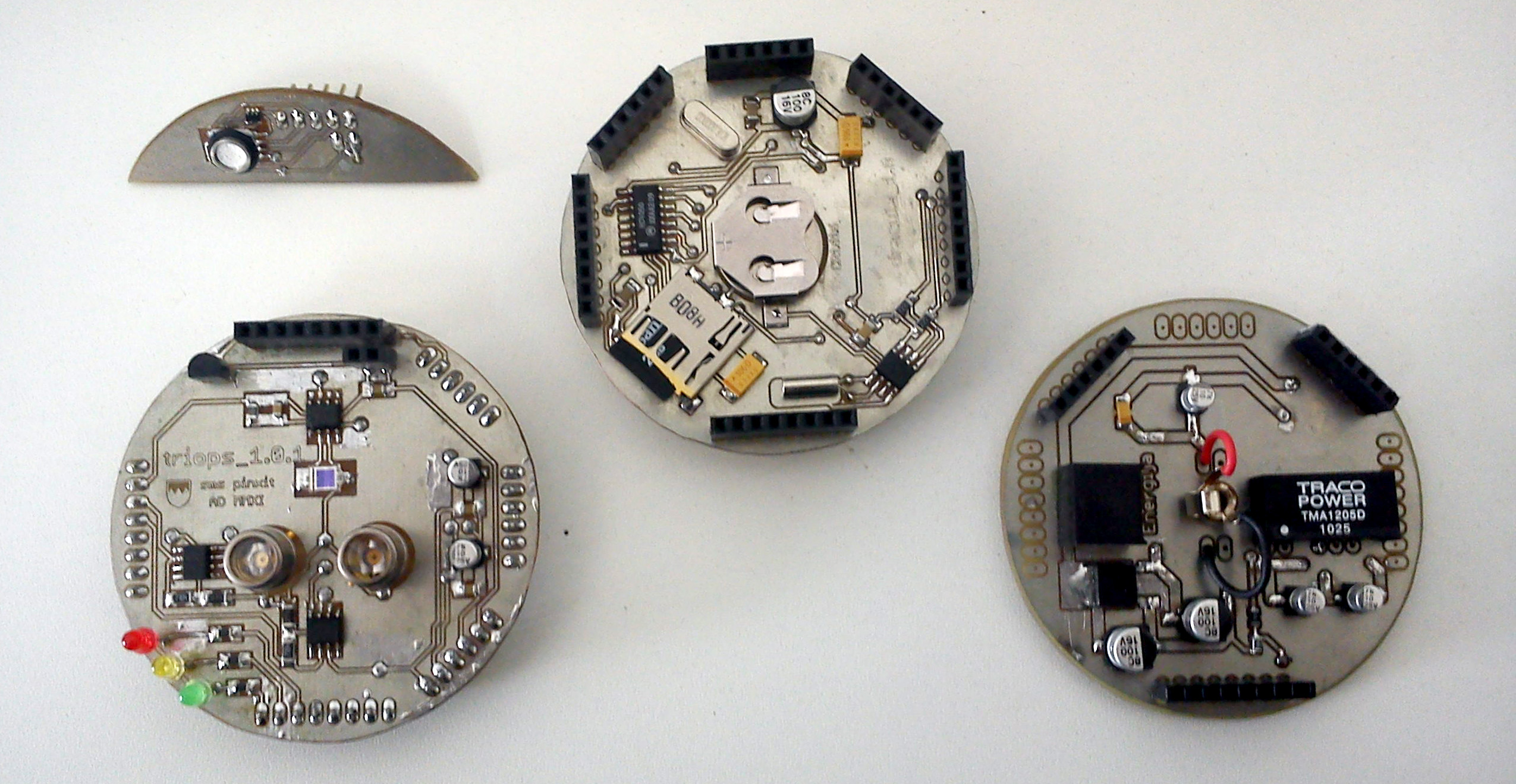
The form factor requires stacking, so I thought of a main board with µP, RTC, µSD and stackable headers. Underneath a power board gets battery power and converts it to the required voltages. On top a sensor board comes with the photodiodes and OpAmps and a conector to the depth sensor, which will be probably mounted in the container wall or so. Actually, we have a prototype of the power board and the main board in the attachments (obsolete but cute, init?), you can nicely see the form factor (which, given it is ever working, will come in handy for CanSat competitions). I cut the 168 of the Mini and soldered a 328 on, but ... see above. Regarding the sandwiched PCBs: we didn't have a better possibility, so we covered single boards with spray paint and burned the tracks with a laser. Precision wasn't good enough for double sided boards, so we glued them together. Not pretty, but working.
In the attachment there are the eagle files. As you can see the SPI brakes out regularly for ISP (with a different conector) and in 3.3V for the depth sensor. I should probably change the Reset line configuration and insert a capacitor, is that right or can I leave it that way?
OK, I don't want to elaborate much more, but feel free to ask. Any advice is appreciated. I never had a formal education in electronics, so I might have done something strange or wrong, please feel free to tell me.
Thank you very much in advance, greetings from Patagonia
Hi all,
well, we emerged to the next step. The miniboard is gone, we have a nice and lean double-sided double-stack, after problems with an Arduino as ISP we successfully burned the bootloader with the adorable USBtinyISP by adafruit and uploaded adafruits sketch for the DS1307 via USB (through my Duemilanove) and - it works!
BUT: there are severe problems in the compiling of sketches which work with the Duemilanove and Mini, depending on the libraries included. For example this sketch here: MS5541 depth sensor communication - #16 by godo - Sensors - Arduino Forum works perfectly well with my 2009 but if I compile it after selecting Sanguino as board I get this:
C:\Users\Sebastian\Documents\Importe ab 0605\arduino-0022\libraries\SPI\SPI.cpp: In static member function 'static void SPIClass::begin()':
C:\Users\Sebastian\Documents\Importe ab 0605\arduino-0022\libraries\SPI\SPI.cpp:23: error: 'SCK' was not declared in this scope
C:\Users\Sebastian\Documents\Importe ab 0605\arduino-0022\libraries\SPI\SPI.cpp:24: error: 'MOSI' was not declared in this scope
C:\Users\Sebastian\Documents\Importe ab 0605\arduino-0022\libraries\SPI\SPI.cpp:25: error: 'SS' was not declared in this scope
If I try something with the microSD card I get:
In file included from C:\Users\Sebastian\Documents\Importe ab 0605\arduino-0022\libraries\SdFat/SdFat.h:27,
                 from Koroljov0_0_1.cpp:10:
C:\Users\Sebastian\Documents\Importe ab 0605\arduino-0022\libraries\SdFat/ArduinoStream.h:40: error: expected `)' before '&' token
C:\Users\Sebastian\Documents\Importe ab 0605\arduino-0022\libraries\SdFat/ArduinoStream.h:70: error: ISO C++ forbids declaration of 'Stream' with no type
C:\Users\Sebastian\Documents\Importe ab 0605\arduino-0022\libraries\SdFat/ArduinoStream.h:70: error: expected ';' before '*' token
C:\Users\Sebastian\Documents\Importe ab 0605\arduino-0022\libraries\SdFat/ArduinoStream.h: In member function 'void ArduinoInStream::readline()':
C:\Users\Sebastian\Documents\Importe ab 0605\arduino-0022\libraries\SdFat/ArduinoStream.h:50: error: 'hw_' was not declared in this scope
C:\Users\Sebastian\Documents\Importe ab 0605\arduino-0022\libraries\SdFat/ArduinoStream.h:54: error: 'hw_' was not declared in this scope
C:\Users\Sebastian\Documents\Importe ab 0605\arduino-0022\libraries\SdFat/ArduinoStream.h:61: error: 'hw_' was not declared in this scope
Which seems to be a major problem regarding something in the programming environment, init? Do I have to mess with the libraries and adapt them, like by declaring all the things the IDE complaines about during compilation?
Unfortunatelly I am quite the programming oger, so if anybody would come up with an idea for a fix it would be greatly appreciated. I already tried the latest Sanguino files from sanguino.cc with 022 version of Arduino IDE.
Thanks very much, greetings from Patagonia
Sebastian
PS: I will add a photo of the stack asap.
Hi folks,
problem solved! I followed the short version here Alternate CORE files for Arduino. Totally awesome!
After cleaning out the /hardware folder and unzipping the content there I selected "Arduino Dunio-644P" and my sketches worked without glitches. Very nice work, msproul, thanks a lot!
In the annex the promised foto. Next step is including the MS5541 communication and the hardware assembly.
The sensor shield is ready. It comes with a UV-A-, a UV-B- and PAR-diode including OPA627 amplifiers as first (UV only) and TL071 amplifiers as second step, and the DS1820. The little board on top contains the MS5541. It actually works, but there are various challenges to face. For example a deadline in three weeks
Hi all,
the prototype did his first job. Someone dropped it down to 10 m depth and water entered. Not so good. Also, the amplification could be higher, or maybe dynamic with a resistor chip conected to the OPA627 feedback loop.
Anyway, after drying everything it still worked perfectly well above surface (which is actually the secondary use of the device). We collected some very pretty graphs of the radiation in Cancun (and seriously, it was work!). So after all, it is somehow successful!
Now we need a better housing and maybe a possibility to readout the SDcard via USB (because this - together with a charging cable - would allow to leave the instrument closed and maybe sealed). I searched a little but found no easy solution. I got some FT232BL chips to build an adapter, but still no clue how to download data files simply as the csv-files they are to a destination folder on my computer.
Any thoughts?
Thanks a lot, greetings from rainy (sic!) Patagonia
Seb
It does seem quite interesting
the arduino probably can transfer the data but probably not very fast
the easiest way I could think is to send the data from the memory card byte at a time, then reconstructing it with a program on the computer
sorta like byte at a time sd data>>arduino>>serial>>pc>>sd data in a continuous loop until the memory card is read entirely
the problem is that is going to be very slow depending how large the file is
Hi,
thanks for responding! @Rob, yes, the card is on the "mainboard". See foto DSC00140.jpg: the board in the middle is the one with the MCU (but on the bottom side) and the clock and card on top. We discarded the cable idea from the begining. @winner, wow, that sounds slow all right. Also, I am not a programmer, so this would take long. Maybe a future approach is a replacement with one of the mightier Atmel chips which already come with USB and the possibility to emulate an USB device. For know I will try to talk my boss out of it and propose very tight sealing and taking the SDcard out for reading instead. That would keep it somewhat much simpler and would require less changes of the design.
I'll keep posting on the development, thanks again!
I don't think it can imitate an sd card tho, it will still need to go through the mcu unless you can perhaps bypass the mcu and maybe have a port to directly read the sd card
or have the arduino act as a usb keyboard and have it read the sd and type it into say notepad
which makes the pc side easier, although idk how much speed it saves
or if you have a wireless component added and can send the data and store if off the mainboard for easy access, with or without mainboard storage as a backup