Hi all,
I need help with powering my project. I have 52 Hall effects sensors and 52 RGB leds (common anode). What it does is when a magnet is near the sensor, the green led turns on and when no magnet, the red led turns on. The red led is controlled by arduino pin while the green one is by the hall effect sensor (blue led is not in use). So far I made it to work with just 3 sensors and 3 led powering from arduino. I know that this setup won't work when i have 52 leds and sensors. I'm using Allegro A3144 which is according to the datasheet draws 25mA, 4.5V-24V and the leds forward current of 20mA, 2V. I have a 12V 1A power supply but I don't think that's enough to power my project. What power options do I have?
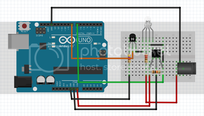
Below is how my sensor and led set up looks like but multiply it by 52. Also, I have 2 megas to use on the project.
Thanks!!
If you have 2 Arduino Megas then that's enough Arduino pins.
The main problem will be your 12V supply. Regulating 12V down to 5V is going to generate a lot of heat (+wastage). You can use a more efficient switching DC converter (eg. this) but it's still quite a lot of amps.
How many amps?
Your sensors don't use 25mA, they can switch up to 25mA through their transistor. For themselves they use 4.4mA (typical) according to the datasheet.
So...each LED+sensor pair needs about 25mA. 52 of those gives 1.3 amps. Add in a couple of Arduino Megas, call it 1.5A total. You should probably get something capable of at least 2.5A to keep things cool/reliable.
Power?
5V@2.5A is 12.5W of power needed in theory.
12V@1.0A (your power supply) is 12W (which converts to 5V@2.4A if we can convert with 100% efficiency).
So...your power supply is just about up to the job, if you get an efficient converter.
That polulo converter claims 90% efficiency which translates to 2.1 amps maximum output using your power supply. We need 1.5A so your power supply will running at about 75% load, ie. it will probably get quite hot. It's up to you, but ... I wouldn't wouldn't do it if it's a cheapo power supply.
You can get a 5V, 3A power supply for less than the cost of that converter. To me that seems a better option.
Why do you need an arduino at all? You can use a transistor to invert the signal from the hall effect sensor and light the red LED.
Then if you want the sensor reading by a controller a Uno with a few port expander will do the job.
Also the data sheet says that the hall sensor takes 4.4mA typically and 9mA maximum. Nowhere close to your 20mA.
Grumpy_Mike:
Why do you need an arduino at all? You can use a transistor to invert the signal from the hall effect sensor and light the red LED.
Then if you want the sensor reading by a controller a Uno with a few port expander will do the job.
Yes, but if you've got some Arduino Megas that need using up, well...it's less wires. 
Yes, but if you've got some Arduino Megas that need using up
Then you still have the problem of communicating between the two.
Thanks guys for the help. And thanks for the correction on the sensors' amps.
@fungus this is really helpful. Just to make it a little complicated, what IF I add a solenoid (12V 600 mAh) Lock-style Solenoid - 12VDC : ID 1512 : $14.95 : Adafruit Industries, Unique & fun DIY electronics and kits in the circuit. Would a 12V 3A enough to power everything? Thanks again for the help.
@Grumpy_Mike I already have 2 megas on hand ( i got 1 for free). I want the red led connected to the arduino pin as later on, I want to be able to blink it or do something with it. But the use of transistor will be very helpful if I abandoned the idea of blinking the red led. Also, I already got the 2 megas to communicate with the help of Master Writer/Slave Receiver example on this site.
Also, with that much current, should I be worrying about the wire gauge for my jumper wires? I'm currently using CAT5e which is according to the label is 24AWG.
I apologize for the follow up questions. Thanks Again.
egglog12:
@fungus this is really helpful. Just to make it a little complicated, what IF I add a solenoid (12V 600 mAh) Lock-style Solenoid - 12VDC : ID 1512 : Adafruit Industries, Unique & fun DIY electronics and kits in the circuit. Would a 12V 3A enough to power everything? Thanks again for the help.
500mA for a solenoid seems suspiciously low....
I'd get a 5V supply for the LEDs and use your 12V supply for the solenoid. If you need a single supply then 12V 3A should be enough, but put a big-ass electrolytic capacitor on the power wires next to the solenoid to give it a kick when it fires. Also a big-ass diode across the capacitor (backwards) to absorb any negative voltage spikes created by the coil when you release it.
egglog12:
Also, with that much current, should I be worrying about the wire gauge for my jumper wires?
A little bit.
It wouldn't hurt to put them in groups and have a power wire to each group.
You can't sink current for 52 LEDs at 20mA each with a Mega - it's limited to 800mA total thru its VCC/GND pins.
@CrossRoads What if I power my 52 leds from another power source and use a transistor like this:
would this be more ideal? Thanks for you help.
Sure. Lot of wiring tho. I'd use a string of shift registers to drive the LEDs, cut the wiring down by quite a bit.
Even easier if you seperate the LEDs, use a single MAX7219 to drive the 52 LEDs, and have a seperate LED that the sensor drives.
Why use so much current through the LEDs? If you're using today's super bright LEDs, my bet is you can cut that current in half and not be able to see any difference in brightness.
@CrossRoads Thank you for catching this. This saves me a lot of time and pain.
