What would be a resonable simple circuit that could take the Arduino outputpin and deliver a 5 maybe up to 10A current to a coil (electromagnet)?
I've tried with a MOSFET (FQP30N06 N-channel, 30A, 60V 0,04mOhm Rds) but it seems only to deliver 2A - somewhere I loose power. The coil has between 2 and 3 Ohms resistance (I have several) I put an extra switch transistor in front to give a higher voltage to the gate (it needs 10V for fully on, if I understand the spec sheet rightly)
It isn't the power supply, that is a large labsupply, and when connecting the coil directly to it, it cheerfully supplies 2-4-8A (whatever I set it's current limit to) and can pulse it, too (I just briefly "clap" the wires) sparks fly and I can see the "magnetic pulse" by the way the pliers jump towards the coil 8)
In an ideal world, the specifications are :
Input signal is from the Arduino.
Power Supply is 12 or 24V (well, to push 8A through 3 Ohms I need 24V) or maybe even more ...
The pulse will be a few milliseconds long, maybe as short as 0.1, so the "rise time" of the coil current should be in the order of ten microseconds. Of course, I dont know the inductance.. so it will just be what it is, but the circuit shoud deliver "full power" as fast as possible
The duty cycle will be of the order 20% at peak times (lasting a few seconds) and down to 1% otherwise, so some overloading is allowed (The coil can only take 2A continuous so at 10A I must keep below 20%)
There are couple questions:
when you try to "energize" the coil, what outputs signal you set on digital pin of arduino?
I mean: PWM or HIGH ?
It possible, that current has no chance to rise due low rate voltage/inductanse?
And schematic drawing would be helpful for father investigation.
Magician:
(1) I mean: PWM or HIGH ?
(2)is It possible, that current has no chance to rise due low rate voltage/inductanse?
(3) And schematic drawing would be helpful for father investigation.
1:HIGH. Plain DC. Full power, nothing less 8)
2:Possibly, when I do the pulsing. At the moment my measurments use simple DVMs and so I hold the signal for 2-4 seconds (until things get - literally - too warm) enough to see. So the current setup isn't working due to a faulty schematic/circuit.
3:Well, my one isnt any good, so I need a new schematic Rather than load you with my errenous preconception I thought it would be easier if you suggested/sketched one for me. For example, should it be pull down to Gnd or pull up to +ve?
But the ones I can find only have 25V and a few A drive if they are "logical FET". So my thought was to put a small switching transistor in front (that also feeds of the +24V) to drag the gate Voltage high enough. But that is the part of the circuit I got wrong (several times). Wrong approach?
I think/hope (could be wrong here) that it is a 5 minute sketch for the experienced circuit designers.
But the ones I can find only have 25V and a few A drive if they are "logical FET". So my thought was to put a small switching transistor in front (that also feeds of the +24V) to drag the gate Voltage high enough. But that is the part of the circuit I got wrong (several times). Wrong approach?
Yes you can drive a higher voltage gate with a transistor but it's a little complicated because of the three different voltages involves (5V and 24V supplies and 10--12V for the gate).
Perhaps the easiest approach is to drive the gate from a voltage divider from 24V down to 10 to 12V or so, and use a small NPN transistor to short the gate to ground to switch off the FET. Try making the voltage divider thus: 10k from gate to ground, 12k from gate to +24V. This should hold the FET hard on - easy to test.
Then a small NPN transistor - collector to gate, emitter to ground, base via a 10k resistor to Arduino pin. Setting the pin HIGH will make the NPN conduct and bring the MOSFET gate to ground, switching it off. Setting the pin LOW will have the opposite effect. Be careful not to leave the pin as an input and HIGH, as this will turn on the weak-pullup resistors and only partially turn on the NPN.
If you want high frequency switching lower the resistance of the potential divider to, say, 470ohms and 560ohms.
Thanks MarkT, I got a circuit diagram from Magician that is along the same lines.
IF the circuit is inverted logic (LOW for ON) there will have to be something inverting in front, so that the coil doesnt turn on until the sketch starts running and decides the on or off. There will be many coils, but only turn on one or two at a time (no, it is not a stepper/direct drive motor - I've thought of using a motor driver shield/circuit, too), so if at power on they all turn on ...
I can see that is a problem I didnt think of in my earlier attempt either. Hmm.. maybe an inverted enable line that is common to all driver circuits?
I have just discovered this forum and while browsing through it came to this thread. The topic is very close to something I wish to do with an Arduino, IE rapidly pulse a electromagnet (though at a lower power level). Is there a way to see or obtain a copy of any sketch referenced by Msquare.
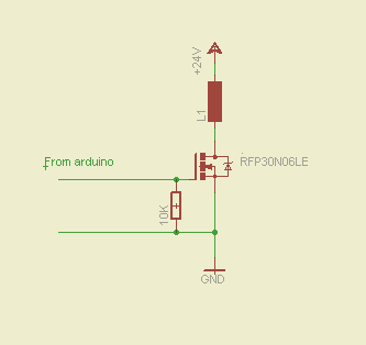
The MOSFET(RFP30N06LE) suggested by Magician works as advertised. I get all the power I want in my coil in the very simple circuit : Arduino pin to the gate (a 10k shorts to ground) and oherwise the MOSFET just drains the load to GND, when the pin is set high.
The project (that has been idle for some while) can continue!
I received a PM from "MChus", asking about the schematic & code. Really, it is that simple, as described in the previous post. Well, being lazy I did buy 3 of these from sparkfun, as it was very convenient with the screw terminals for my prototype. And another 10 of the RFP30N06LE for the actual machine. Note the 10K resistor making sure gate is off when the Arduino is unpowered. I'll add a flyback diode accross the coil on the next circuit to protect the MOSFET.
I have slightly moved away from the orginal spec. My coils are used for mechanical actuator and to get a fast/firm enough pull I am now using 24V and thus using more than 10A. It required a beefy powersupply, too. This is well within the MOSFET spec, but too high for the coils, but as I pulse them shortly with a dutycycle well below 20% I suspect I am safe. Well, no smoke yet
The code is as simple. digitalWrite on and off as any LED blink example I do not use delay() but timers as outlined here and I use the microseconds() for better resolution.