Would appreciate any comments or suggestions on the following circuit diagrams for a home alarm system.
Living out of a big city and in Africa, deliveries are slow, so I need to complete my 'shopping list' right the first time.
Diagram 1 is for the output via an optocoupler to power a 12V siren and strobe light.
Diagram 2 is same as diagram 1, but using a MOSFET to power the devices. Which would be the better option to use ?
Diagram 3 is for INPUT of an alarm activation by breaking the magnetic door or window contacts.
When armed, pin 5 registers LOW. When the contact is broken, the optocoupler is inactive and the 10K pull up makes pin 5 detect HIGH.
Diagram 5 is a passive infra-red motion detector. runs on 12V and has a built in relay (N/O) which will change to N/C when motion is detected. The program will look for the input pin to be LOW to detect the motion trigger.
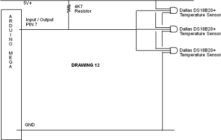
Diagram 6 connects multiple DS18B20 temperature sensors to a single pin.
Schematics look OK to me, but I am no electric engineer.
With the delivery modus you mention I can only advice you to order enough spare parts, mistakes happen, malfunction devices happen, and you will allways have the possibilty to extend your system .
Schematic 1 - wrong, not enough current optocouple could supply, driver required.
Schematic 2 - wrong, as already pointed out resistor missing.
Schematic 3,5 - wrong, output transistor of the optocouple is inverted
(collector must be connected to V+ rail).
3,5, the opto LED is wrong way around as well, just flip the whole component.
2, wouldn't you have a resistor pulling the gate to 12v?
2, is that a logic-level MosFET? If not it may not fully turn on.
So drawing 1 must be deleted as the optocoupler is not capable of powering any external devices without something like a MOSFET or Relay to boost the power to the device.
Drawing 2. Are you saying that I should, on the optocoupler, have the transistors collector to 12V+, and the transistors emitter to 2 resistors to reduce the power to the MOSFET, (and a pull down resistor to prevent any floating of the gate pin ?) ?
The link is to the opto, but never mind I googled the FET.
It has a typical Vgs(th) (threshold voltage) of 1.5v so that means it will be well turned on by 5v. Apart from that the second bullet point on the data sheet says "logic level gate drive".
Also, it would be safe to remove the LED from the drawing ?
Yes, just look at the current-limiting resistor, that will need to be upped.
3 and 5 are now right.
2, I'm not a FET expert, but I think as you are actively pulling the gate down (off) this needs a pull up resistor on the gate to ensure it turns on when the opto is not active. Now that we've determined this is a logic level FET I guess that pull up could go to either 5v or 12v. In this situation I don't think you need a series resistor on the gate, the small and infrequent inrush current will not harm the opto.
So drawing 1 must be deleted as the optocoupler is not capable of powering any external devices without something like a MOSFET or Relay to boost the power to the device.
Another thing to think about is the line length and environment for the wires on the FET. FETs are quite prone to ESD so while this is OK on paper it is not a good design I think for the real world.
I'd either use a transistor instead or have the FET throw a small (onboard) relay that in turn operates the remote siren etc.
If you do this you can ditch the opto as you get isolation with the relay.
Graynomad:
The link is to the opto, but never mind I googled the FET.
It has a typical Vgs(th) (threshold voltage) of 1.5v so that means it will be well turned on by 5v. Apart from that the second bullet point on the data sheet says "logic level gate drive".
Thanks Rob. Explains why I could not see the wood from the trees.
Graynomad:
2, I'm not a FET expert, but I think as you are actively pulling the gate down (off) this needs a pull up resistor on the gate to ensure it turns on when the opto is not active. Now that we've determined this is a logic level FET I guess that pull up could go to either 5v or 12v. In this situation I don't think you need a series resistor on the gate, the small and infrequent inrush current will not harm the opto.
So if I convert drawing 2 to drawing 8, then the MosFET will remain in a Off - non-conductive state until I power the optocoupler from the boards Pin.
Graynomad:
Another thing to think about is the line length and environment for the wires on the FET. FETs are quite prone to ESD so while this is OK on paper it is not a good design I think for the real world.
I'd either use a transistor instead or have the FET throw a small (onboard) relay that in turn operates the remote siren etc.
If you do this you can ditch the opto as you get isolation with the relay.
Would the ESD affect the D/S line of the MosFET, or only the Gate side ? The distance from the optocoupler to the Gate will be very short ( centimeters ) whereas the distance from the D terminal to the external device can be between 3 and 40 meters.
I think...(pauses for FET expert to step in)...that ESD is a problem on all terminals and that 40 metres is asking for trouble.
If you drive the FET directly from the Arduino and have it drive a small relay then the C and NO terminals of the relay can control the siren and they are immune to everything.
I may not be right about the ESD but at least I'm safe
Graynomad:
I think...(pauses for FET expert to step in)...that ESD is a problem on all terminals and that 40 metres is asking for trouble.
If you drive the FET directly from the Arduino and have it drive a small relay then the C and NO terminals of the relay can control the siren and they are immune to everything.
I may not be right about the ESD but at least I'm safe
Rob
Thanks again Rob.
So I can't replace both the opto and the FET with a small 5v relay, as the relay requires 0.2A which, I 'think' is too much for the board output pin.
Also I can't keep the opto and replace the FET with a relay, as the opto can't power the relay.
So would need either :
the pin driving a transistor ( like 2N2222A ) driving the relay, or
the pin driving a FET driving the relay.
I was hoping for a silent option, that's why I was looking at the MosFET in preference to a relay.
the pin driving a transistor ( like 2N2222A ) driving the relay, or
the pin driving a FET driving the relay.
Yes.
I was hoping for a silent option,
Then I'd replace the FET with a power transistor. That should do the same job and AFIAK normal transistors aren't overly worried about the real world. You would have to look at the heat dissipated though if the siren needs a lot of grunt, OR, use a small transistor with a relay up at the siren.
Drawing 7 is close (and right to have GND on the long wire BTW) but flip the opto transistor so the collector goes to the Arduino and emitter to GND. (The LED side is right.)
OK. I think that I can live with the occasional relay noise, so for simplicity, I have changed to the following :
Diagram 9 is for the output to power a 12V siren and strobe light via a 5V relay.
Diagram 11 is for INPUT of an alarm activation by breaking the magnetic door or window contacts.
When armed, pin 5 registers LOW. When the contact is broken, the optocoupler is inactive and the 10K pull up makes the Input pin detect HIGH.
Diagram 10 is a passive infra-red motion detector. runs on 12V and has a built in relay (N/O) which will change to N/C when motion is detected. The program will look for the input pin to be LOW to detect the motion trigger.
Diagram 12 connects multiple DS18B20 temperature sensors to a single pin.