I'm working on a project where the direction from a DC motor will trigger different actions. I've done a lot of things the other way around (using arduino so control direction), but not with the motor as input. I found a thread on the old forum, but it didn't get into any specifics of how to do this, just speculation about using diodes and capacitors to charge up in different directions and then take an input reading. I think this has probably been done before- does anyone have any links or ideas as to how to test things (I want to be sure I'm doing so I don't accidentally damage the arduino with a voltage spike)
I'm thinking with a couple of lamps (rated >= VMOTOR), a couple of rectifiers, and a couple of photocells. You could determine/infer direction and applied PWM.
Maybe you could do it with LEDs, too, I suppose, but I'm figuring the lamps would be more "self-sufficient".
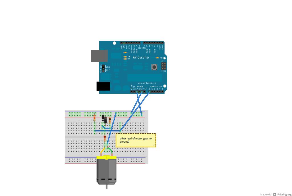
(See attached dwg.)
I gather you want to have the motor being rotated by some external mechanical force, and then want a circuit and method to read the induced current and determine the direction and maybe speed that the motor is turning. Do I have this right?
Can you clarify what sort of motor we're taking about, and what sort of function/force/input is spinning it? How fast do you expect it to spin?
Assuming my guesses are right, I think you could place a voltage divider network a smoothing capacitor and a zener diode for voltage clamping and get a pretty decent reading of motor speed and direction via an analogue input.
yes that is correct! it is a small geared dc motor and the mechanical action is cranking to generate power. this is just a prototype to see how people interact with the decide so we are not focusing on the power generation, just the response to certain actions.
so yes i would like to read the direction of cranking in one direction to trigger one action and the direction in the opposite direction to trigger another since it will be input to the arduino it won't be more than 5 volts
The capacitor value is not very important, use 0.1uF.
You need a 10K from the analogue input to +5V, and a 20K from the analogue input to ground. Then a 20K from your motor to the analogue input and a capacitor from the analogue input to ground. Finally you need two diodes connecting to the analogue input as well. Anode to analogue input cathode to +5 and Cathode to analogue input anode to ground.
Then read the value of the analogue input. You will get about 512 with no movement, then it will go up or down depending on the movement of the motor / generator.
Hook up one side of the motor to a voltage divider so the motor is at 2.5V, and connect the other to an analog input.
The analog pin will now read 512~ when not turning. a reading above 512 indicates rotation in one direction, and a reading less that 512 means rotation in the other direction. Depending on how fast it can be rotated the voltage should stay within bounds. Might still want a cap to smooth out the signal to the analog input.
You want to use a high speed motor - in building Brushless motors for model planes they call this KV which is the constant for Volts per Thousand RPM. A motor with a lower KV will also produce more voltage at a lower RPM. rotating it by hand should not yield very high RPMs on the motor shaft.
gardner:
Assuming my guesses are right, I think you could place a voltage divider network a smoothing capacitor and a zener diode for voltage clamping and get a pretty decent reading of motor speed and direction via an analogue input.
Yes, sounds reasonable, but the negative voltage when its going in reverse could be an issue unless
you bias the circuit to 2.5V at rest.