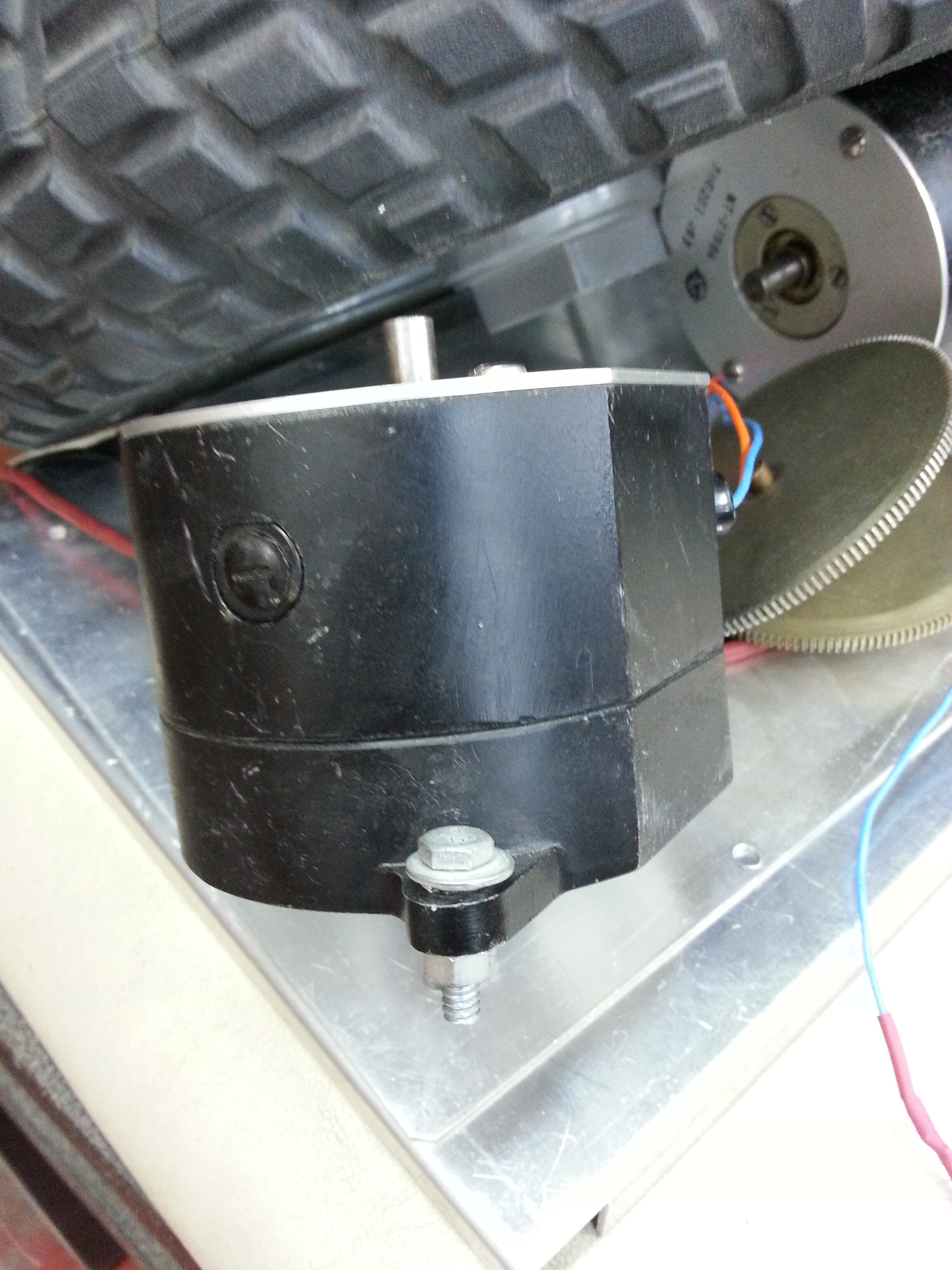
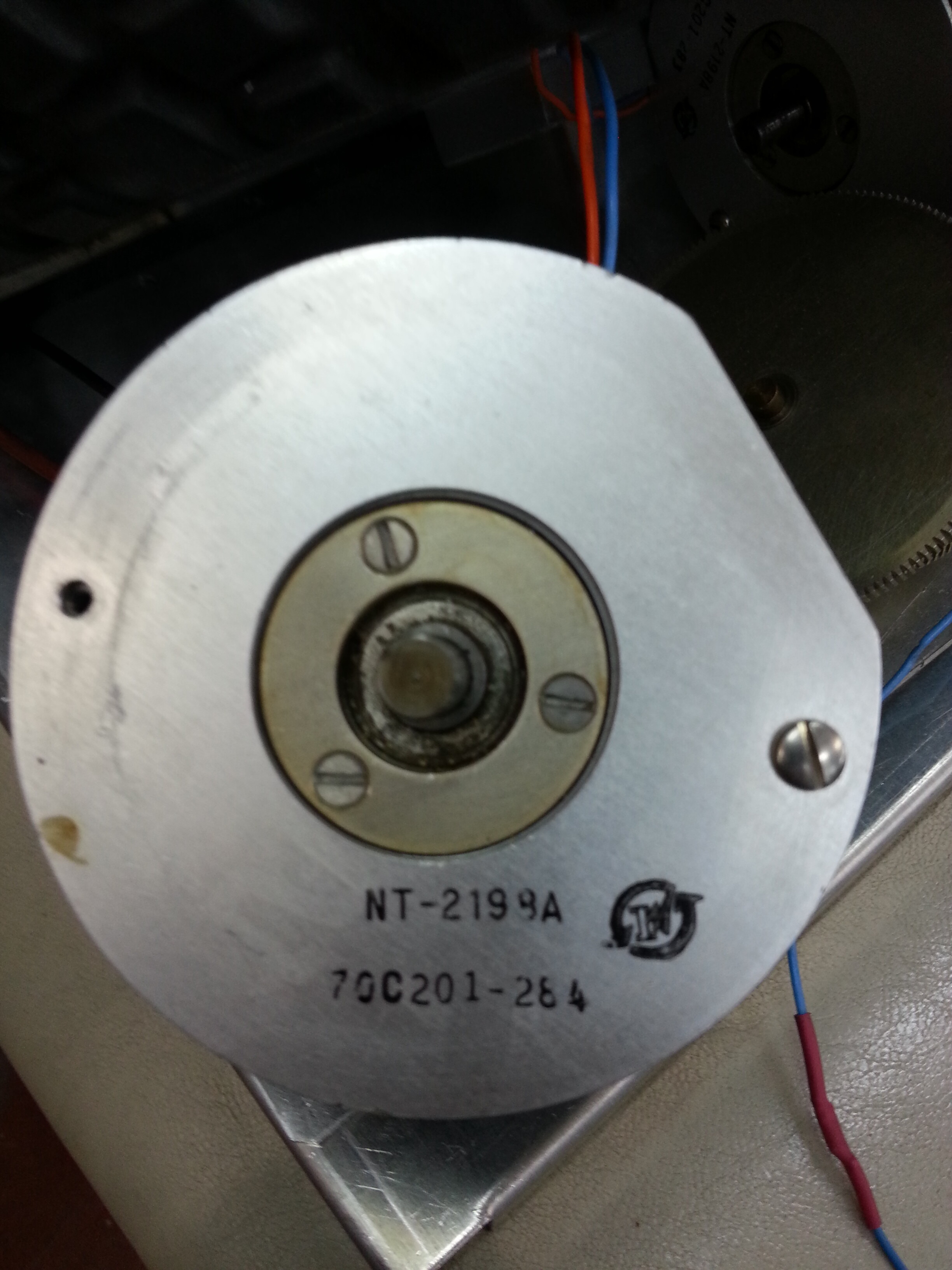
I'm building an arduino controlled two wheeled segway type robot. I've stumbled across two DC motors which seem to be ideal for this purpose, the problem is that I don't have their datasheet and I can't seem to find their parameters anywhere. I can't even identify the manufacturer.
I've attached a couple of photos of the motor in question. Any help would be greatly appreciated.
No, they are obscure. Seem to be standard brushed PM DC motors. Key parameters
are:
motor constant in Nm/A or V/(rad/s)
winding resistance
max speed
You can measure the first two, but the max speed you'll have to estimate.
If you have a tachometer you can measure the rotation speed for a fixed
supply voltage directly, which you can then convert to volts-per-radian-per-second.
This then tells you the newton-metres-per-amp directly, they are the same
constant.
A motor of that size will probably go to 3000 or 4000 rpm (300 to 400 rad/s)
happily. Given the motor constant that will suggest a convenient operating
voltage.
The power dissipation depends mainly on the size, so coupled with the winding resistance
will indicate roughly the continuous current it can handle.
MarkT:
If you have a tachometer you can measure the rotation speed for a fixed
supply voltage directly, which you can then convert to volts-per-radian-per-second.
This then tells you the newton-metres-per-amp directly, they are the same
constant.
Question for you... I had the impression that the voltage in the motor constant, when expressed as V.s/rad, referred only to the back-EMF. So when the motor is at peak no-load speed with constant current:
Vterm = I*R + Vemf
the number that you care about is really Vemf, which is the terminal voltage less the motor current times the winding resistance.
Consider two geometrically & magnetically identical motors, one wound in Al and the other wound in Cu. The former will have higher winding resistance, but they will have electromagnetically identical behaviour (i.e. same current/torque relationship) because the current takes the same path. If you measure the motor-constant using current & torque, they will both give the same answer. To get the same answer with voltage implies that you are measuring the Vemf and not the terminal voltage.
Or am I missing something there?
Anyway, with your typical cheap crap little DC motor, the voltage lost to winding resistance can be significant, so if you want to measure motor-constant, you need to be aware of that. You must measure all of terminal voltage, current, winding resistance and speed in order to arrive at a motor constant:
MC = omega * (Vterm - I * R)
omega = RPM * 2 * pi / 60
Typically under no-load conditions the voltage drop due to IR losses is
negligible, and is still reasonable at full rated load (say 10% of supply),
since that gives a good stiff motor response.
Really small and cheap motors though will skimp on winding copper and
perform worse. Also friction tends to be a higher relatively speaking in
small motors.
This applies to any permanent magnet motor including DC, BLDC, and
PM AC motors, since the magnetic field is fixed.
Motors wound with aluminium would typically have a larger volume
of winding so the resistance is comparable with copper - the overall
weight is about the same for equal performance and Al is a lot cheaper
than Cu these days. Al would motors do need to be bigger and thus
more steel is needed, but steel is also cheap (even silicon steel laminations)
compared to copper.