Hello all,
I am an Intern at Lexmark printing and my summer project is automating our fuser robot to make one of our technicians job a little bit easier. Essentially the fuser robot feeds paper through it until the fuse roll has reached temperature stability. Once this has happened, the fuser robot pauses the paper feed and sends a signal to the arduino board of 5V. This is done through the use of an opto-isolator. The stepper motor connected to the arduino then turns on and feeds our unfused sample. While the sample is being fed, the arduino sends a 0V signal to the fuser robot. Once the sample is done, the arduino sends a 5V signal to the fuser robot telling it to resume paper feed and look for stability again.
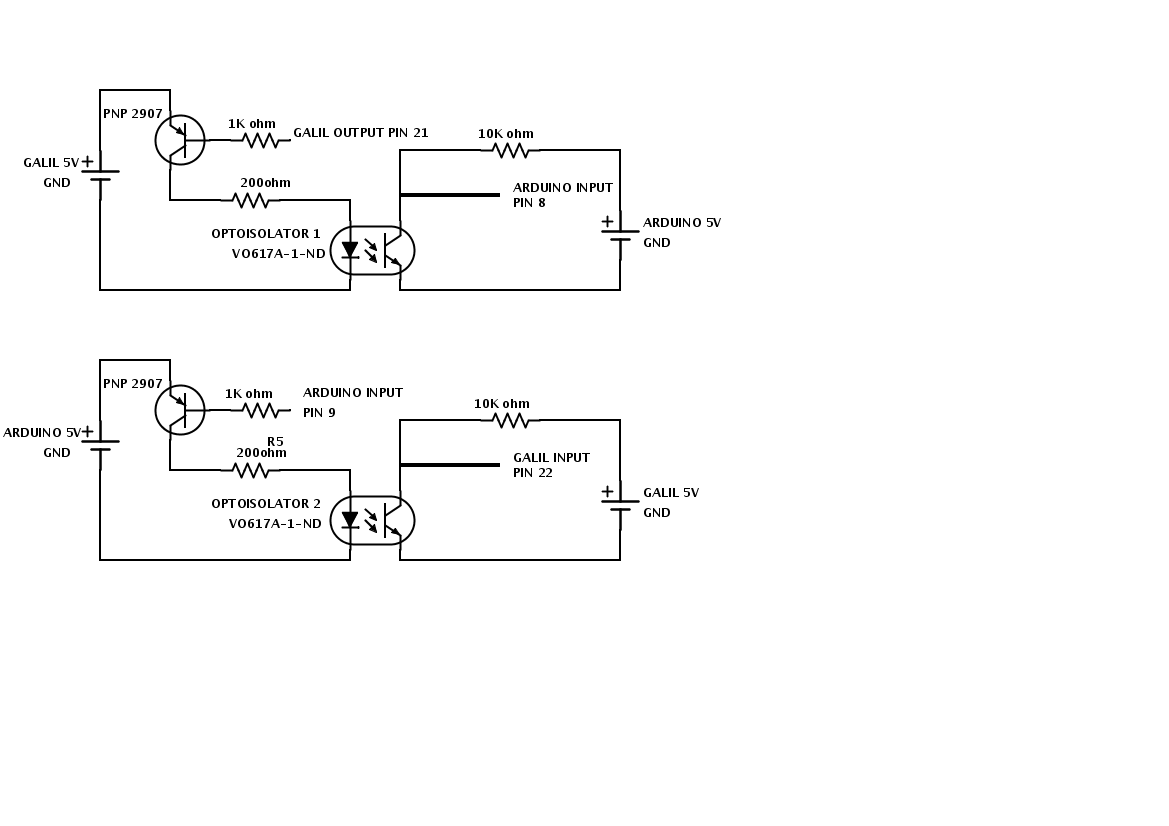
The problem arises with the opto isolator. The fuser is sending a signal through the green wire going from pin 21 of the galil to the base of a PNP transistor in the attached diagram, but the optoisolator is not turning on and my digital line is not picking up the signal on the other side. My digital line is going to pin 8 of the arduino in the picture and is marked by a yellow wire. The fuser robot is marked as galil per the software that it uses.
The opto isolator is from digikey part number VO617A-1-ND
the transistor in the bottom left portion of the diagram is reading 5V on the collector, the base, and the emitter and the 200 ohm resistor is also reading 5V. However i can not pick up the signal on the upper left portion of the opto isolator circuit. The transistor pins in the upper right of the circuit are labeled wrong and i have already fixed this.
The digital line going to pin 8 of the arduino was picking up a signal, however, it was just getting the 5V from the upper power supply rail (arduino) marked with a red wire in the upper left portion of the opto isolator circuit.
If anybody could give me some guidance as to what might possibly be going wrong, that would be great.
Thanks a bunch in advance for all the help.
~Brandon