Ok, the range of LCD pin 3 to GRND is: +1V to -7.1V
EL inverter like this one?
http://www.ebay.com/itm/12V-Battery-or-Transformer-Power-Inverter-EL-3-meter-10-feet-Foil-Wire-Constant-/251107233479?pt=LH_DefaultDomain_0&hash=item3a77284ec7
Ok, the range of LCD pin 3 to GRND is: +1V to -7.1V
EL inverter like this one?
http://www.ebay.com/itm/12V-Battery-or-Transformer-Power-Inverter-EL-3-meter-10-feet-Foil-Wire-Constant-/251107233479?pt=LH_DefaultDomain_0&hash=item3a77284ec7
Foolios:
Ok, the range of LCD pin 3 to GRND is: +1V to -7.1V
Hmm...
A positive voltage should not be possible.
How is the pot, and pins 3 and 18 wired up?
The voltage should vary between the voltage on the 2 legs of the pot.
1 leg should be ground
The other leg should be pin 18 or Vee.
The wiper (the center connection) is what connects to pin 3 and where the
voltage is being measured.
Vee is normally negative like negative 7 to 10 volts and then
ground is well ground.
So the voltage should vary between gnd and whatever Vee is (pin 18).
EL inverter like this one?
http://www.ebay.com/itm/12V-Battery-or-Transformer-Power-Inverter-EL-3-meter-10-feet-Foil-Wire-Constant-/251107233479?pt=LH_DefaultDomain_0&hash=item3a77284ec7
Yes. But there are some out there that run off lower voltages that might be better if you want
to power it from something other than 9-12 volts.
--- bill
Ok, checked it again today.
Connections are:
Pot leg 1 to LCD pin 18
Pot leg 2(center leg/wiper) to LCD pin 3
Pot leg 3 to GRND
With knob of pot to farthest twist to the right possible:
Leg #1 of pot is -9.6V
Leg #2(wiper) is -9.6V
Leg #3 is 0V
LCD pin 3 is -9.6V
LCD pin 18 is -9.6V
With knob of pot to farthest twist to the left possible:
Leg #1 of pot is -9.6V
Leg #2(wiper) is 0V
Leg #3 of pot is 0V
LCD pin 3 is +0V
LCD pin 18 is -9.6V
Thats more like what I would expect. ( -9.6v to 0v)
What is different between things now and in reply #20 which was (-7.1v to +1v) ?
Do the pixels now change when you rotate the pot?
--- bill
I have plugged it into a different usb port the second time. I will try to find the point at which I got -7v.
The pixels stay at the same contrast.
It isn't the -7 that seems odd, it is the > zero that is puzzling me.
Maybe the ground the meter was using was not a good ground?
I'm still very puzzled by the pixel contrast not changing when the voltage on Vo is changing
from gnd to -9.6v
It should be going from every pixel being on/black to all pixels off.
--- bill
It's ok tho. I am really glad it has a working display. I'm kinda bummed that I can't get the backlight to work. I am going to assume I blew it out.
I have another of the exact same lcd. I haven't touched it yet. I should be able to get this one lit up without problems now. I am going to go over everything one more time to try not to blow out the backlight this time.
If it doesn't light up, then more than likely the diagram isn't exactly right for this lcd. I will go back to the first one and mess with the two holes at the side of the display to see if those are the backlight pins.
Thanks for the help all.
Foolios:
If it doesn't light up, then more than likely the diagram isn't exactly right for this lcd. I will go back to the first one and mess with the two holes at the side of the display to see if those are the backlight pins.
Maybe not, it might need a very low resistor value - how low did you go?
I have some glcds that use 3-4 ohms.
It could also be an EL backlight model.
The safest way to test an unknown backlight LED after you tried 330, 165, and 110 ohms,
(assuming you hook up 2 then 3 in parallel)
would be to get a multi turn pot say 50 ohms, hook it up
to the backlight and slowly turn it to reduce the resistance to see if the backlight lights up.
From the earlier photos, it looks like there are traces running to header pins 19 and 20.
See if you can see where they go.
All the glcds I've got (3 different ones) have holes on the side like yours but are soldered
to the backlight LED module.
It could be that the PCB can be stuffed with either a LED backlight or an EL backlight.
Can you post a couple of clear closeups of the back of the glcd?
--- bill
Take a look at this Pacific Displays datasheet:
I think this may explain it.
Take a look at page 2. It appears to have a magic decoder ring for the
information below the model number.
In your case it is: FC-R-ET-6-V-T
While not an exact match - since it isn't quite the right data sheet.
-R seems to imply:
Reflective (no backlight)
Sounds like the panel doesn't have a backlight.
Follow the traces for pins 19 and 20 and see if you can see where they go.
Also look carefully at the side of the display.
Often with displays that don't have a backlight you can see under it all the way through
the long ways.
--- bill
The first part # posted has an EL backlight... but an inverter is only $3.00 - $6.00
Doc
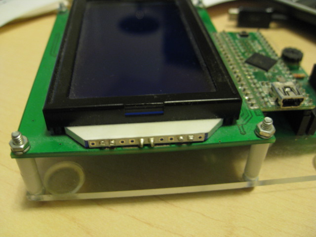
Also look carefully at the side of the display.
Often with displays that don't have a backlight you can see under it all the way through
the long ways.
You're right, there is a gap all the way across between the lcd and the circuit board.
So there's no backlight. Now does that mean there is no EL backlight as well? I don't know the difference.
EDIT:
Or would I need to do something like this:
(See attachment)
I think I got my answer here:
http://www.mp3car.com/general-hardware-discussion/3432-el-backlight-inverter.html
ELbacklight_Guide.pdf (1.11 MB)
Without looking directly, it's hard to tell for sure but from the photos so far, it looks like
there is no backlight.
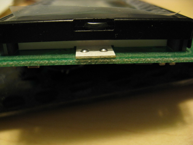
Attached a blue backlight panel that uses an EL backlight.
You can see the EL layer sticking out on the right and it is soldered
to the PCB.
I've also looked at 3 other glcds and a few non glcds that use LED backlights.
(I attached two other glcds with LCD backlights)
In all cases - even those that have the backlight attachments on the side vs
on the header, the backlight has connections that are soldered to the PCB.
On the ones where the backlight has to be powered from connections on the side,
there the 4 holes. The backlight uses the two inner holes and the wires for power to the backlight use
the outer holes.
In the photos in reply #8 and #28 there is nothing soldered to the backlight connections
on the PCB.
So my suspicion at this point is that there is no backlight.
--- bill

Ok, that makes it very obvious. Thank you for posting those.
Alrighty then. On to soldering this onto a pcb. A new adventure awaits. =)
