Murdock's library is obviously wrong. If you try to use the set clock function, it does not operate at 2 MHz. It operates at 8 MHz which is the wrong timing for ADC.
Great that you have taken the time to look through the code and seem to have found a bug, but please elaborate. I cannot find a fault in the code.
Datasheet pages 22 and 23 list the desired serial clock frequency, which is a maximum of 1/10th the clock speed. I try to achieve that by using delayMicroseconds() to delay the write and read code. The whole code takes a bit longer in reality but this method makes sure that the code is never faster than the ADS1213.
This code (from the initalization routine) calculates the desired delay in microseconds for half a clock cycle (the cycle is delayed twice: once for clock high, once for clock low):
int _tscaler = (clockspdMHz)10;
byte _SCLKdelay = 510/_tscaler+1;
clockspdMHz is a float which is given in the initialization routine. If you give 2.0, _tscaler will be 20. _SCLKdelay will then be 3, giving a maximum SCLK frequency of 166kHz.
So I don't see what you mean, it doesn't run at 8MHz. If you use the ATMega's built-in SPI (= TWI) hardware, then it runs at 8MHz standard. My code doesn't use that.
I realize this is an old thread at this point and I hope some are still following it as I have a question about interfacing with an ADS1211. After reading through several posts including this one, I am trying to use the library Murdock posted on Apr 19, 2011 (ADS1213) to log data from a geophone. I've read through the spec sheet for the ADS1211 several times and think I have a beginners handle on how it works.
I followed the wiring diagram from the first post on this thread, including using the arduino's internal timer but all I get out is a bunch of 0's. I also tried to follow nadabro's post (Arduino Forum) as he is working with the same sensors and ADC. Is there anyhting that I might be missing? I would like to use the internal clock instead of an external crystal if possible but if that is my problem please let me know.
I'm sure you need more information to help me so please let me know what you need. Right now my code is the example code for switching channels in the library (I like to start with the examples until I understand them enough to change them for my needs). Thanks for any help you can provide.
Hi dkolbay, the latest version of the library (compatible with Arduino 1.0) is here (from the march 28th 2012 post up there ^).
With these kind of problems, it's always wise to take a step back in order to analyze the problem, then determine the simplest test possible, and then try to get it working.
Yours is obviously not working correctly or it wouldn't be spewing out zeroes. There can be problems somewhere in the communication, but the most obvious problem is that the clock signal (not serial clock) you are feeding to the ADS1211 is not correct. But let's first devise a simple test, as your sketch right now involves multiple write and read operations, too many opportunities for errors.
The simplest test would involve as few operations as possible and as simple feedback as possible. This could be 1) writing to the command register that Vbias must be on, making Vbias output some voltage and 2) reading this voltage with an analog Arduino pin. You can make a sketch to do this test and make it output a victorious message when the test succeeds.
If you want to feed a clock signal to the ADS1211, you'll have to configure one of Arduino's timers to do so. Timers are quite simple pieces of hardware, they simply count and when they reach a number, they do something. You can read all about it in the Atmega328's datasheet (it might seem overwhelming but keep in mind that timers are very simple devices, albeit with many configuration options). What you want is to 1) take a timer that controls a port that is not used by the library and 2) make it produce a square wave (thus output 0v and 5v with equal periods).
So if you have the test sketch that outputs a square wave to the ADS1211's clock input, writes to the command register and sets the Vbias high, and then reads the Vbias voltage on an analog Arduino pin, you can hook everything up and start testing. If it still doesn't work, you only have a few things to check. If it does work, hooray, and you can start expanding the code to fit your needs.
I dug in my sketches folders and found some code to output a square wave on a pin using a timer, I use it for producing tones with a speaker. The .h file (it's just a C file, you can open it with the Arduino IDE) contains the functions that set the timer and set tones. The .ino file houses an example sketch. It does a lot of direct register manipulation using bit math. The constants like "TCCR2A" that you see in the code are defined in the avr/io.h file (Arduino includes it automatically I believe), they are simply bits of code that write or read a register (in the "TCCR2A" case) or define where a port bit is in the register with a number between 0 and 7 (in the "OC2A" case), and _BV(n) is function that shifts a binary 1 n places to the left (1<<n).
I hope this helps you solve the problem, and if not, come back here with some more details.
Hey Murdock,
I've also been trying to use the library and the wiring diagram that you provided in the original post. The library I'm using is the one from March 28th, 2012 so I know it's compatible with Arduino 1.0 software. The problem I am having is that the code seems to get stuck on the constructor portion of the code and I've found that it starts to fail at the point when defining the high/low instructions for the data ready portion.
I believe be code is something like while(!(PIND & _BV(_DRDY))); - don't have the code in front of me as I'm typing this so typing from memory. I've measured the voltage coming out of the data ready pin and its low until the serial monitor is brought up and then it jumps up to high which I assume is fine. I'm not sure why the constructor is failing at that particular point and was wondering if maybe it has to do with where the data ready pin is located? I've set the data ready pin to 4 on the arduino so I know that it falls between the constraints you have in the constructor and can't for the life of me figure out why it won't go past this point in the constructor. Any help would be greatly appreciated.
Some basic information:
- wired it to the same wiring diagram you provided earlier with the crystal in being located on pin 3
- data ready pin 4
- IO pin 10
- Sout pin 12
- Sclk pin 13
- CS pin 8
- Running the standard deviation example you provided running into noninverting channel 1 and grounded the inverting channel 1
- "Debugged" by using the pin 13 LED to turn on and just went through section by section.
- haven't gotten to the rest of the code thou because the constructor is failing right now and therefore can't go beyond that point.
Hi MrInternet, good that you're debugging step-by-step. There is no while loop in the constructor itself, but it does call the 'write' function to write the settings to the register. The while loop in the write function looks like this:
  while (!(PIND & _BV(_DRDY)));  // wait for ready to go high
  while (PIND & _BV(_DRDY));     // wait for ready to go low
It is in there to make sure that you're writing to the register at the beginning of a 'low' DRDY period, because if you're only starting to write at the end of the DRDY period, it might end before the commands are written.
I don't understand why invoking the serial monitor would have anything to do with the DRDY pin of the ADS1213. Invoking it just restarts the Arduino.
It seems that you're having the problem that the DRDY pin is not following the standard pattern of high/low, it must be high or low all the time, resulting in the statement within the while loop always being true, thus causing an infinite loop. However, if the ADS1213 is functioning correctly, the DRDY pin will go high/low in a certain pattern (which you can find in the datasheet).
You have been debugging down to a basic level: you've been testing a simple case of communication between the Arduino and ADS1213. But as the DRDY pin of the ADS1213 might not function correctly, it's wise to check if the ADS1213 itself is even working properly, there might be a problem with the crystal for example. So what you can do is write a simple script for the Arduino that polls the ADS1213's DRDY pin and then tells you something about the signal, like how many times it went high/low in the last second. Then, you can see if the ADS1213 is working or not.
Thanks for the response,
I was testing the DRDY pin at the exit from the ADS itself and was noticing that it would be low, which would indicate data being ready, until I opened the serial monitor itself which would force the DRDY pin to go high, Data not ready, and stay there. This wouldn't change according to a normal pattern and would just be a single fluctuating (a couple of millivolts) value. I did try changing out the ADS1213 to make sure it wasn't an issue with the pin itself and thankfully the other ADS had the same issue.
I'll make sure to check that the crystal it properly working as well because that may be the issue. Thank you again for your response and for the library.
Hi,
First of all, thanks for all your work you put into this.
I am trying to use this library with a ads1211 and a arduino mega 2560, but no luck so far.
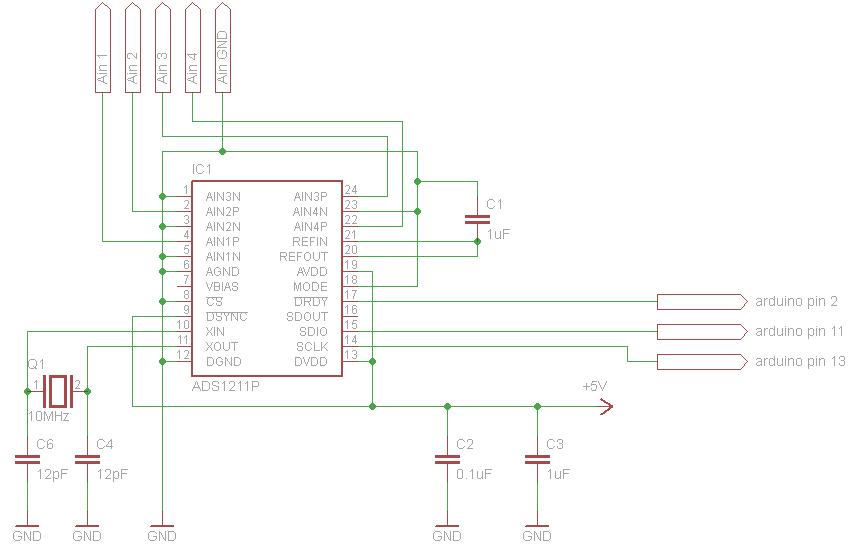
Basically I'm connecting the ads1211 as shown here and using the channel shift example sketch that comes with the library.
I am using Pin 13 and 11 for SDIO and SCLK, and Pin 20 for DRDY.
I am using a 2MHz crystal and have also tried 4 and 8 MHz too.
My problem is that it doesn't do anything, the sketch stops at the CMRwrite command (as it doesn't print "done with setup").
Does the library work with the Arduino mega 2560 and the ads1211?
If yes, what could I be doing wrong?
Greetings,
Tillman
chillman, I'm curious if you ever got this working. I'm getting the same symptoms when trying to interface an ADS1211P with a UNO.
Connected exactly as per Murdock's other thread. Sometimes the Uno won't even get as far as "ADC_ext.CMRwrite(3,B001,1,16,300);", I put a println in before it to debug where it's locking up, and it seems to happen fairly regularly when running "ADS1213 ADC_ext(2.0,true,13,11,2,5);".
I put the include and the above line into a blink sketch, and it froze that too. Pin 13 never sets as output.
I don't have the necessay skillset to debug any further, hopefully someone else has seen and fixed this issue.
AtticusG3, I'm having exactly the same problem.
One interesting thing that I've found though: I have a 10MHz crystal that I put between Xin and Xout, when I use this crystal and set ADS1213 ADC_ext(10,false,13,10,4,8), nothing happens, but when I replace the clock speed of 10 to 8 in the sketch, I do get some output that looks like:
...
1 ch -657
1 ch -17089
1 ch 1907
1 ch 2168
1 ch -5345
1 ch -2589
1 ch 1952
1 ch -4401
1 ch -9173
1 ch -5136
1 ch -5996
1 ch -2237
1 ch 5612
1 ch 1199
1 ch -14100
...
This just looks like random numbers to me, but at least it's some sort of response. I have a thermistor connected to Ain1P and set the basic channel shifting sketch to only scan channel 1. I'm not able to get any response using the internal arduino clock.
Hello!
I am trying to make it work with ADS1210 and arduino pro mini (5V, 16MHz)
ADC connected to 8MHz quartz (Xin and Xout)
this my code:
#include <ADS1213.h>

ADS1213 ADC_ext(8,true,13,11,2,0);
// clock speed MHz, true=offset binary (false=two's complement (can be negative)), SCLK pin, IO pin, DRDY pin, CS pin (0 if not in use)

void setup() {
  Serial.begin(9600);
  ADC_ext.CMRwrite(1,B001,1,1,255);
  // channel 1, mode 001 (self-calibration), gain 1, TMR 1, DR 255
  Serial.println("Done with setup");
}

void loop() {
  static byte Channel=1;
  Serial.print(Channel,DEC); Serial.print(" ch ");
  Serial.println(ADC_ext.read(B0000,3),DEC); // Read and print the signed value
  delay(500);
}
NegInput connected to ground
PosInput conncted to Vcc (5V)
This is result in port monitor:
Done with setup
1 ch 0
1 ch 16777215
1 ch 4740951
1 ch 0
1 ch 0
1 ch
And that is all - system stops
16777215 - it is OK, but zero and 4740951 - what is it?
And usually code dies at constructor
I know this is an old topic, but I wanted to bring something up that I just figured out while trying to get this working.
I am trying to use an Arduino Micro for a project, and I keep having the dreaded "Arduino not showing up under ports" problem, wherein I have to press the reset button directly before the IDE starts uploading the program in order for it to work.
Usually successfully uploading something fixes this issue (until it randomly decides to happen again), but today, it was doing it EVERY time I tried to upload.
I just downloaded and installed the new 1.6.4 IDE, so I tried downgrading to 1.6.3 that I was POSITIVE was working with my micro earlier.
So I narrowed it down to this library.
If I upload the "blink" example program using the "reset right before upload" method, the micro is fixed, and it shows up under the ports as it should.
If I then #include the library, but not use it, it also works fine and shows up under the ports.
As soon as I try and execute any of the commands within the library (ANY of them), the arduino disappears from the port list after the upload is finished, and the program does not execute (the light doesn't blink or anything, I'm still uploading "blink", just with a call to this library in it)
So I'm thinking maybe the bootloader is somehow locking up on reset? I can't seem to figure out what's going on, but I thought I would just try and bring it up.
I am going to try with my Uno tomorrow since it has a seperate USB chip, unlike the micro. I think that's where some of the issues are coming from.
This thread was a great read, though! Lots of great information about SPI.
Yes, it has something to do with the USB-on-chip bootloader thing on the micro.
It might be my circuit, though, because my Uno still locks up before the setup function, although it isn't lost to the wind (So I can use serial monitor for debugging, which is nice)
More troubleshooting, yay!
EDIT:
Yeah, ignore everything I previously said. It was my circuit.
I thought I grabbed 12pF caps for the crystal on the ADC, but I guess I grabbed 12uF... It wasn't oscillating, hence the 'duinos locking up waiting for a reply from the chip or something.
I don't have any 12pF's, but I did find some 10pF, now it works fine.
EDIT EDIT: works fine... with the Uno. I still can't get it to work on the Micro, so I'm not exactly sure what's going on. I'm just going to stick with the uno now.
Sorry for the necro