Different behaviour of Analog ports (A0 vs Ai)

Hi there,

I noticed that, reading the analog ports from the serial monitor the value is very different depending the port (A0 or Ai). If I don't connect anything to the analog ports the A0 stays very stable on 1023, while the others are not so stable are around 850.

(By Mult+/- I understand + or - of a digital multimeter. Ai all other analog ports but A0)
I measured these values:

| Mult+ | | Mult- | | Value |
| - | - | - |
| 5V pin| | GND pin| | 4.9V |
| A0 pin| | GND pin| | 4.9V |
| Ai pin | | GND pin| | 0.02..0.03V |

After running this code:

void setup() {
  // initialize serial communication at 9600 bits per second:
  Serial.begin(9600);
  pinMode(A0, OUTPUT); digitalWrite(A0,LOW);
  pinMode(A1, OUTPUT); digitalWrite(A1,LOW);
  pinMode(A2, OUTPUT); digitalWrite(A2,LOW);
  pinMode(A3, OUTPUT); digitalWrite(A3,LOW);
  delay(20);
  pinMode(A0, INPUT);
  pinMode(A1, INPUT);
  pinMode(A2, INPUT);
  pinMode(A3, INPUT);
  delay(50);
}

I get these results:

| Mult+ | | Mult- | | Value |
| - | - | - |
| 5V pin| | GND pin| | 4.9V |
| A0 pin| | GND pin| | 0V |
| 5V pin | | A0 pin | | 4.88V |
| Ai pin | | GND pin| | 0.01V |
| Ai pin | | 5 V | | 0.0V |

Running this cod:

void loop() {
  // read the input on analog pin 0:
  int sensorValue[10];
  int delayTime = 10;
  sensorValue[0] = analogRead(A0); delay(delayTime);
  sensorValue[1] = analogRead(A1); delay(delayTime);
  sensorValue[2] = analogRead(A2); delay(delayTime);
  sensorValue[3] = analogRead(A3); delay(delayTime);
  sensorValue[4] = analogRead(A4); delay(delayTime);
  sensorValue[5] = analogRead(A5); delay(delayTime);
  sensorValue[6] = analogRead(A6); delay(delayTime);
  sensorValue[7] = analogRead(A7); delay(delayTime);
  sensorValue[8] = analogRead(A8); delay(delayTime);
  sensorValue[9] = analogRead(A9); delay(delayTime);
  
  // print out the value you read:
  for(int i=0; i<=9; i++){
    Serial.print(sensorValue[i]);
    Serial.print(" ");
  }
  Serial.println();
  delay(100);        
}

On the Monitor I get these values:
1023 787 668 693 562 473 405 357 310 291
1023 795 716 661 638 548 484 418 351 318
1023 802 748 686 697 612 554 481 398 354
1023 812 759 725 711 650 599 533 437 392
1023 822 760 758 695 661 614 565 462 424
1023 831 760 777 677 660 615 580 478 447
1023 837 765 773 680 658 615 585 492 462

So whatever I am doing the A0 behaves different from Ai. Why? What can I do to make them behave similar?

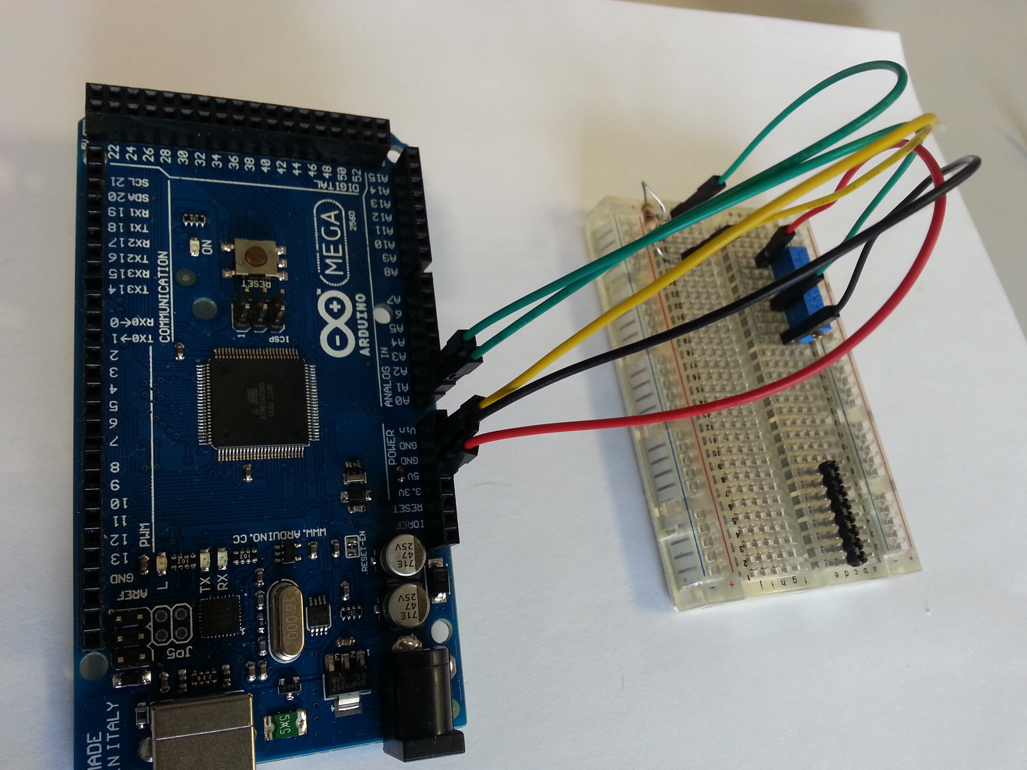
I am using Arduino Mega 2560.

Greetings,
Emoke.

If I don't connect anything to the analog ports

Then the input is floating and all measurements are meaningless.

Connect each input to the wiper of two separate 10K pot with the ends connected to ground and +5V and they will work like you expect.

Running this cod:

Most cods swim and do not run due to lack of legs.

If the pin is left floating, then you are in violation of the specs and really can't expect anything sensible. You can't leave input pins floating.

  1. You all right, but I think even if I don't connect anything to them (floating), they should work similar. The A0 is stabile at 1023 while the others not.

  2. I didn't write previously, but if I connect all of them to a pot, this strange behaviour still remains. To be more specific: if I connect a pot to A0, the Serial Monitor shows 950, when I connect the same pot, without changing anything, to Ai it shows 250. Why?

but I think even if I don't connect anything to them (floating), they should work similar.

No there is no reason why they should.

if I connect a pot to A0, the Serial Monitor shows 950, when I connect the same pot, without changing anything, to Ai it shows 250. Why?

Because you still have something wrong. That simply will not happen, they might differ by a few but not by that much. There is a possibility you could have damaged your Arduino but more probable is you are doing something wrong.

Until you post the code, schematic and photo of this experiment it is hard to say what is wrong.

Make sure you connect all 3 pins of the pot. One end goes to gnd, the other to +5V. The wiper (usually the middle connection) should be connected to your analog input.

void setup() {
  // initialize serial communication at 9600 bits per second:
  Serial.begin(9600);
  pinMode(A0, OUTPUT); digitalWrite(A0,LOW);
  pinMode(A1, OUTPUT); digitalWrite(A1,LOW);
  pinMode(A2, OUTPUT); digitalWrite(A2,LOW);
  pinMode(A3, OUTPUT); digitalWrite(A3,LOW);
  delay(20);
  pinMode(A0, INPUT);
  pinMode(A1, INPUT);
  pinMode(A2, INPUT);
  pinMode(A3, INPUT);
  delay(50);
}

Can some one explain me why there is pinMode(A0, OUTPUT) and pinMode(A0, INPUT); in the setup? I mean you put the pin to read and write?

Can some one explain me why there is pinMode(A0, OUTPUT) and pinMode(A0, INPUT); in the setup?

Easy it is that emoke doesn't know what he is doing, which is fine because he is asking the question here. It is largely irrelevant because once you use analogRead the pins are configured for analogue input and so over ride anything that has gone before.

I mean you put the pin to read and write?

Actually I think it only sets it to write as the last statement overrides the first.

marco_c:

I mean you put the pin to read and write?

Actually I think it only sets it to write as the last statement overrides the first.

Then read so? pinMode(A3, INPUT);?
Loop functions seems fine. But setup. Really i need get some more information.

Hi there.
First of all, thank you for your interest in helping me with my issue.

Second, answering @FirstName:

  1. While I described that the read values, when I don't connect anything to the pins, showed by the Serial monitor are:
1023 787 668 693 562 473 405 357 310 291
  1. and the A0 is very stable on 1023
    1,2=> the A0 behaves as it would be continuously at high (pullup).

So, to be sure that it is not the case, I make from the analog pins outputs (pinMode(Ai, OUTPUT); as suggested in http://arduino.cc/en/Tutorial/AnalogInputPins) and I pull them down (digitalWrite(A1,LOW):wink:
After this I make from the same pins inputs, in order to use them as analog input pins.

As conclusion these lines are to be sure that my analog pins are not leaved in HIGH. (as suggested in Details and Caveats in the same page cited previously).

The analogRead command will not work correctly if a pin has been previously set to an output, so if this is the case, set it back to an input before using analogRead. Similarly if the pin has been set to HIGH as an output, the pullup resistor will be set, when switched back to an input.

Please read the given link before posting some irrelevant answer. I hope that now you can understand why I did that.

Dear marco_c and others.

The circuit is very simple, I really don't think I make something wrong with it. The connections are as suggested in http://arduino.cc/en/Tutorial/AnalogInOutSerial. The difference is that I don't use the LED feedback part. I tested it with a 50k and 200Ohm potentiometer as well (evidently not at 50k, but at the midle). I measured with the multimeter the midle pin's resistance in respect to the outside pins (at the 50k pot the outer was the midle, at hte 200ohm pot the midle was the midle). So everithing is fine. I unpluged everthing and pluged one several times, to be sure that I didn't connect anything in a wrong way.

In the second "experiment" I use the A0 and A1 (with or without the described setup). I connect a 1k res to the A1. The program is:

void loop() {
  // read the input on analog pin 0:
  int sensorValue[10];
  int delayTime = 100;
  sensorValue[0] = analogRead(A0); delay(delayTime);
  sensorValue[1] = analogRead(A1); delay(delayTime);
  
  // print out the value you read:
  for(int i=0; i<=1; i++){
    Serial.print(sensorValue[i]);
    Serial.print(" ");
  }
  Serial.println();
}

Serial monitor shows:

1015 0

Than I change the two "cables" between the A0 and Ai. The same program.
Serial monitor shows:

1021 863

Why is not equal 1015 to 863 and a 1021 to 0? Why is it enaugh 200Ohm to pull down the A1 and not to A0? Both of the values (1015 and 863) are changing if I change the pot value.

Thanks for reading.

Please print all of the code that you are running, it might be relevant. Are you trying to connect anything to the external voltage reference pin on the CPU? What do you connect the other end of the resistor to, ground or +5V? If ground then ok on A1.

Are you writing a 1 to A0 pin while it is in input mode? That's how pullups are enabled on the digital pins. That doesn't seem like the problem, since the resistor should have pulled it down anyway. Unless it's in the rest of your code somewhere, the A0 pin looks like it is not working.

Hi afremont. Thanks for your answer. In the next sentences you will find my answers and precisions.

Please print all of the code that you are running, it might be relevant.

All my code now:

void setup() {
  // initialize serial communication at 9600 bits per second:
  Serial.begin(9600);
}

// the loop routine runs over and over again forever:
void loop() {
  // read the input on analog pin 0:
  int sensorValue[10];
  int delayTime = 100;
  sensorValue[0] = analogRead(A0); delay(delayTime);
  sensorValue[1] = analogRead(A1); delay(delayTime);
  
  // print out the value you read:
  for(int i=0; i<=1; i++){
    Serial.print(sensorValue[i]);
    Serial.print(" ");
  }
  Serial.println();
}

Are you trying to connect anything to the external voltage reference pin on the CPU?

No. You can look at the attached image.

What do you connect the other end of the resistor to, ground or +5V? If ground then ok on A1.

One end of the resistor is connected to GND, and the other at the pin. Everithing is logic regarding the Ai ports, exception is the A0.

Are you writing a 1 to A0 pin while it is in input mode? That's how pullups are enabled on the digital pins.

That is the whole program that I use. Is simple as that. When I received the arduino board, the first day I worked with it at midnight, so I really don't remember what I did. It is really possible that I was writing 1 at A0 as well, but not after that.

That doesn't seem like the problem, since the resistor should have pulled it down anyway.

Yes. I think as well. But it is not happening that at A0.

Unless it's in the rest of your code somewhere, the A0 pin looks like it is not working.

As you can see from my simple code. The A0 should work as A1, but it is not. Because when I change the A1 in put cable with the A0 input cable, they don't give the same result.

Hope that's helped.
Emoke.

@emoke
I have just run that code with the addition of a startup function that just contains a serial begin. The result is that I get exactly the same number on A0 and A1 when I swap over the pot's wiper from A0 to A1. The analogue input not connected shows a floating input. I am using a Uno.

Therefore, if this is not what you are getting, your system then it is either broken in some way or you are not doing what you think.

@Grumpy_Mike

Thanks. And probably all the ports when are in floating "position" are unstable and the neighbours of a pin present similar values. What you presented is the logical, normal way of going (it should be like that). However I hope that is not hardware issue (even if from the first moment it seemed to be), while it is sensitive to resistivity variation, but he tries to remain at high. This is I don't understand why.

There are lots of things in the electronics that could go wrong. At a pure guess I would say it is likely that the FET controlling the connection of the pull up resistor is faulty giving it a pull high. This would not stop an external voltage over riding it but would stop it reading the same as the others because the pulling high and the impedance of the voltage source are acting as a voltage divider to give some what more than the input voltage.

As I say only a guess. Is it better with the 200R pot than the 50K pot?

When I plug in the Arduino works (as described in the first comment), as in the Table:

TABLE 1
Mult+ | Mult- | Value
5V pin| GND pin| 4.9V
A0 pin| GND pin| 4.9V
A0 pin| 5V pin| 0 V
Ai pin |GND pin| +-0.02..0.03V
Ai pin |5V pin| +-0.02..0.03V

Of course the +-0.02..0.03V’s meaning is undefined.
After the measurements I run this:

void setup() {
  // initialize serial communication at 9600 bits per second:
  Serial.begin(9600);
  pinMode(A0, OUTPUT); digitalWrite(A0,LOW);
  pinMode(A1, OUTPUT); digitalWrite(A1,LOW);
  pinMode(A2, OUTPUT); digitalWrite(A2,LOW);
  pinMode(A3, OUTPUT); digitalWrite(A3,LOW);
  delay(20);
  pinMode(A0, INPUT);
  pinMode(A1, INPUT);
  pinMode(A2, INPUT);
  pinMode(A3, INPUT);
  delay(50);
}

// the loop routine runs over and over again forever:
void loop() {
}

Now the outpus are:

TABLE 2
Mult+ | Mult- | Value
5V pin| GND pin| 4.9V
A0 pin| GND pin| 0V
5V pin | A0 pin | 4.88V
GND pin| A0 pin | 0 V
Ai pin | GND pin| 0.01V
Ai pin | 5 V | 0.0V

If you look at the two tables you can see, that the result of the code it was that the A0 port went down to a stable 0, while the other ports are undefined as well. (Ai behaves in a normal way).

The I run this all:

// the setup routine runs once when you press reset:
void setup() {
  // initialize serial communication at 9600 bits per second:
  Serial.begin(9600);
  pinMode(A0, OUTPUT); digitalWrite(A0,LOW);
  pinMode(A1, OUTPUT); digitalWrite(A1,LOW);
  pinMode(A2, OUTPUT); digitalWrite(A2,LOW);
  pinMode(A3, OUTPUT); digitalWrite(A3,LOW);
  delay(20);
  pinMode(A0, INPUT);
  pinMode(A1, INPUT);
  pinMode(A2, INPUT);
  pinMode(A3, INPUT);
  delay(50);
}

// the loop routine runs over and over again forever:
void loop() {
  // read the input on analog pin 0:
  int sensorValue[10];
  int delayTime = 100;
  sensorValue[0] = analogRead(A0); delay(delayTime);
  sensorValue[1] = analogRead(A1); delay(delayTime);
  
  // print out the value you read:
  for(int i=0; i<=1; i++){
    Serial.print(sensorValue[i]);
    Serial.print(" ");
  }
  Serial.println();
}

Thse Serial monitor reads:

1023 941

Where 941 is changing a little bit all the time, while 1023 is stable.

If I plug out then in the Arduino and I measure one more time the potential differences I will get the Table 1.

So it is something like this. I can pull down the A0, but after I do anything else he will pull up. I hope that now it is really easy to understand my board behaviour.

Thanks.

Thanks for the information. Even at that manner :).
Maybe this will help you. Some info about your micro-controller:

1 (100 KB)

Just a point when you say:-

When I plug in the Arduino works ........
After the measurements I run this:

It implies that you might think that when you plug it in the arduino is not running anything. In fact it is running the last sketch you programmed into it without you having to load anything into it. Every time you load a new sketch it resets the processor which is the same as unplugging it and plugging it back in again.
Apologies if you knew that but your wording implied you might not.