Hello everybody,
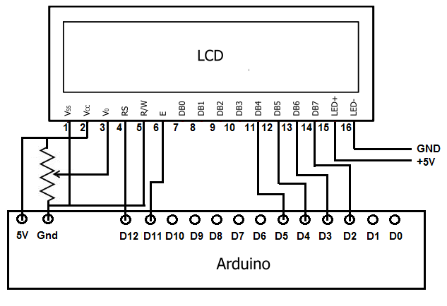
I replaced the LCD on my 3D printer and tried using the old one with my Arduino Uno. The LCD is a 20x4 character one with 16 pins. It is on a shield with 5 more buttons and the necessary resistors. I followed the PCB traces and wired it to the Arduino like this.
After uploading a LiquidCrystal example sketch and changing the display to 20x4 the LCD displays nothing or weird characters. It would be nice if somebody helped me.
It would help if we could see the message that you are trying to display and the 'weird' characters that result.
Make sure you do your testing with a 'static' message, ie. nothing between the { } brackets in loop().
Don
This is the code I'm using:
// include the library code:
#include <LiquidCrystal.h>

// initialize the library by associating any needed LCD interface pin
// with the arduino pin number it is connected to
const int rs = 12, en = 11, d4 = 5, d5 = 4, d6 = 3, d7 = 2;
LiquidCrystal lcd(rs, en, d4, d5, d6, d7);

void setup() {
  // set up the LCD's number of columns and rows:
  lcd.begin(20, 4);
  // Print a message to the LCD.
  lcd.print("hello, world!");
}

void loop() {

}
The display is just blank and not showing any text.
We can't check your wiring with the photos that you have provided.
- We have to be able to verify that you followed the PCB traces correctly.
- We have to be able to unambiguously follow each wire from one end to the other.
Don
EDIT: With a second look I think you may have D4 - D7 hooked up exactly wrong. The yellow wire from pin 2 looks like it is going to what is probably D4.
This is the wiring:
No. That is a drawing of how the wires should be connected. We need to be able to follow your actual wires on the actual hardware.
Here are the PCB traces:
Unfortunately that picture doesn't show which pins D4, D5 and D6 go to on the connector, and the connections on the other side of the board are hidden under the display. What did you come up with and have you double checked? One would assume the pins are sequential but you never can tell.
EDIT: Comparing the board to the fritzing diagram it looks like the connections in your diagram make sense and the pins are not quite sequential. Are you SURE you connected them correctly?
Under what conditions does your display show weird characters? As long as something shows up under some conditions we can assume that the contrast setting (controlled by R2 and R3) is OK.
Just curious, why did you replace the display on your printer?
Don


