I'm simulating the controller of a slot car race track. It's a really simple controller, the plug has 2 contacts and inside the controller we find a linear potentiometer (10kohm). At 10kohm the car doesn't move and at 0ohm the car goes at max speed.
It seemed straight forward enough to introduce a digital potentiometer/rheostat to replace the slot car controller. I chose the MCP4162 (10kohm).
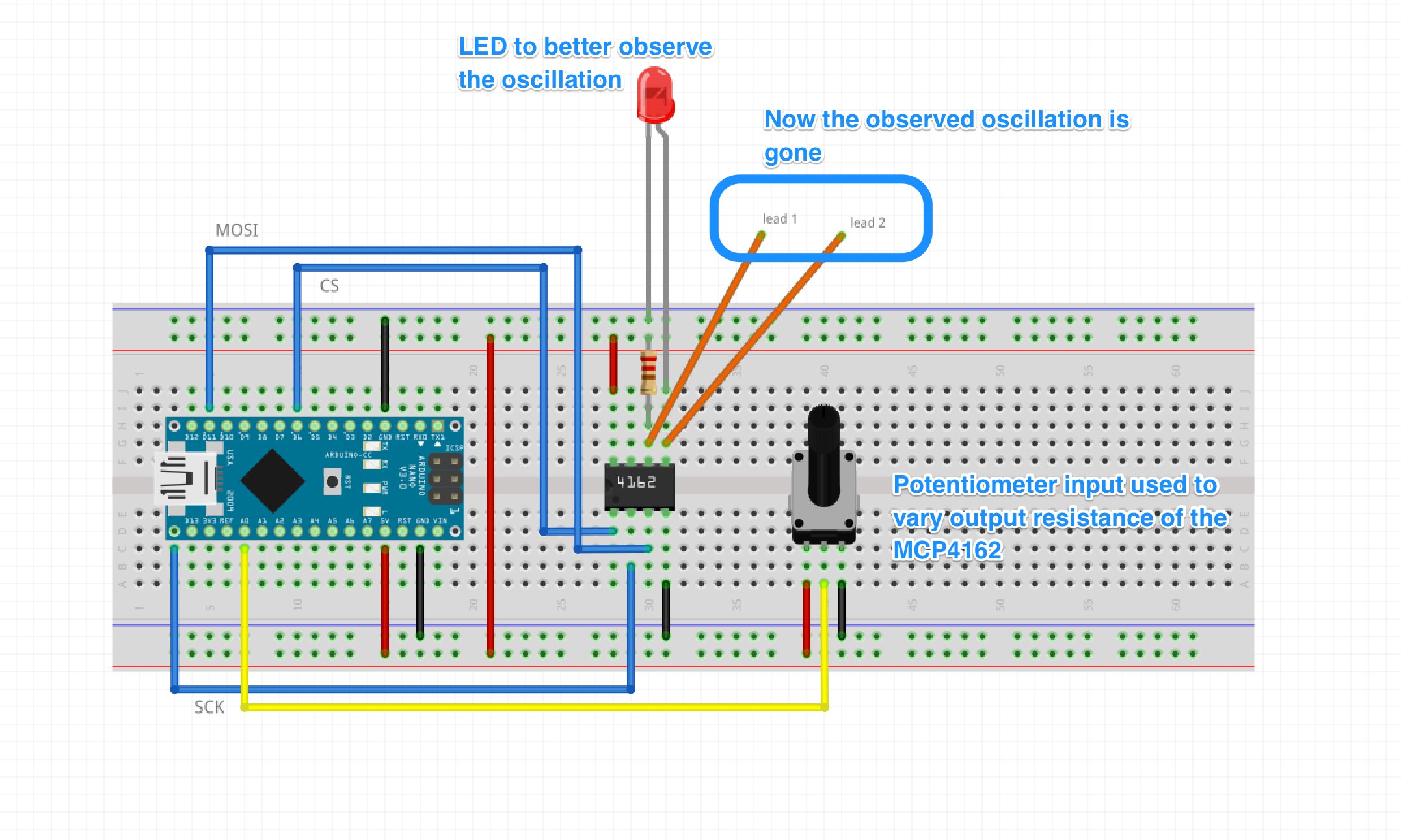
What I did was put together the breadboard as seen in the image below. I used a pot-meter input to drive the output resistance of the MCP4162. When measuring with a digital multimeter it appeared to work well, getting stable and constant resistance readings when not changing the input pot's value.
I then attached 2 wires to the outputs which were connected to the slot car system (effectively replacing the controller, correct?).
The observed behavior of the race track was an erratic, oscillating amount of input to the slot car race track. I'd say ~0.5Hz oscillation. Not 0 to max, I'd say ~0 to ~25% input (2.5kohm?). I don't have an oscilloscope so I can't get really good readings so I'm kind of guessing. The digital multimeter doesn't display things very well.. it seems things are changing too rapidly for the digital multimeter to be useful.
I thought I might see the oscillation more clearly if I would introduce an LED to the schematic. Oddly, the oscillation was not visible anymore. However, the slot car needed a lot more input to get going, the car started moving when the potmeter was almost fully open. The image below show the wiring.
I'm not sure what's going on here. Can the MCP4162 not act as an 'isolated' resistance? Is it necessary to have common ground? Eh.. is it even needed to have common ground? The MCP4162 is simply a variable resistor, is it not? I don't understand the oscillation but also not why the added LED changed that behavior.
Any insights are welcome!
You also have to understand the circuit you are connecting to because the the resistor chain in the digital potentiometer cannot normally be considered as islolated from the rest of the package. You are effectively joining two circuits together (a) your arduino and the digital pot and (b) the model car controller. As has been pointed out, these devices usually have low maximum power and voltage tolerances specified in the data sheet.
I guess the model car controller is suitably isolated from the mains supply, but you have to consider the voltage across the pot and the maximum current when the pot is at near zero resistance. Is one of the terminals on the original pot connected to ground in the model car controller circuit? I guess that somehow it is part of a voltage divider.
Introducing a led powered by the Arduino circuit and series resistor in that combination is likely to have mysterious side effects like the ones you have reported.
There are methods of achieving completely isolated control in similar applications using an opto coupler, pulse width modulation and a low pass filter (basically an op amp and a few external components). However, again you'd have to understand the target circuit.
Skimming the datasheet told me that the pot can source/sink no more than 20 mA on any output, and can handle no more than 12V on its inputs.
If you connect the LED over the pot, this will act as parallel resistance for your race car, making the effective resistance very low. This should get your car to near max speed at all times - but that's just my understanding from what you describe, and those horribly unreadable Fritzings you posted. I wonder how that LED would even light up, as it doesn't seem to have any power supply.
MarkT:
Can you please provide full details of the slot car controller?
Of course.
controller as-is
view of the plug, showing just 2 connections
controller open
controller showing just the bare electronics
The pusher unit simply moves the wiper across the linear potentiometer. Seems like the controller is nothing more than a variable resistor (10kOhm) to the slot car system, would you agree?
I'm simulating the controller of a slot car race track. It's a really simple controller, the plug has 2 contacts and inside the controller we find a linear potentiometer (10kohm). At 10kohm the car doesn't move and at 0ohm the car goes at max speed.
It seemed straight forward enough to introduce a digital potentiometer/rheostat to replace the slot car controller. I chose the MCP4162 (10kohm).
What I did was put together the breadboard as seen in the image below. I used a pot-meter input to drive the output resistance of the MCP4162. When measuring with a digital multimeter it appeared to work well, getting stable and constant resistance readings when not changing the input pot's value.
I then attached 2 wires to the outputs which were connected to the slot car system (effectively replacing the controller, correct?).
The observed behavior of the race track was an erratic, oscillating amount of input to the slot car race track. I'd say ~0.5Hz oscillation. Not 0 to max, I'd say ~0 to ~25% input (2.5kohm?). I don't have an oscilloscope so I can't get really good readings so I'm kind of guessing. The digital multimeter doesn't display things very well.. it seems things are changing too rapidly for the digital multimeter to be useful.
I thought I might see the oscillation more clearly if I would introduce an LED to the schematic. Oddly, the oscillation was not visible anymore. However, the slot car needed a lot more input to get going, the car started moving when the potmeter was almost fully open. The image below show the wiring.
I'm not sure what's going on here. Can the MCP4162 not act as an 'isolated' resistance? Is it necessary to have common ground? Eh.. is it even needed to have common ground? The MCP4162 is simply a variable resistor, is it not? I don't understand the oscillation but also not why the added LED changed that behavior.
Any insights are welcome!
wvmarle:
Skimming the datasheet told me that the pot can source/sink no more than 20 mA on any output, and can handle no more than 12V on its inputs.
If you connect the LED over the pot, this will act as parallel resistance for your race car, making the effective resistance very low. This should get your car to near max speed at all times - but that's just my understanding from what you describe, and those horribly unreadable Fritzings you posted. I wonder how that LED would even light up, as it doesn't seem to have any power supply.
I apologize if the Fritzing sketch was unclear. I created it for this post, thought it would be much clearer than anything I could draw up. To answer your question about the LED: the flow is
Anyway, I made some resistance/current measurements over the Carrera controller with the system powered on:
Resistance values over the slot car controller:
when not connected to slot car system: 9,5kOhm
when connected to slot car system when it's off: 8kOhm
when connected to slot car system when it's connected to power adapter (rating 14,8V@0,7A): here it gets odd. The reading is higher than anything my DMM can measure (>20MOhm). When I press the controller about 25% I start getting readings, which start at about 200kOhm and as I press it down fully that drops down to 0Ohm
current values over the slot car controller:
when connected to powered slot car system and at 0% throttle: 0.25mA
when connected to powered slot car system and at 100% throttle: 0.50mA
Can anyone explain why the resistance readings get different when connected to the system? As for current, at max 0,5mA I don't think I'm really stressing the MSP4162 digital potentiometer too much.
bombarie:
I apologize if the Fritzing sketch was unclear. I created it for this post, thought it would be much clearer than anything I could draw up.
A rough pen and paper sketch tends to be a lot clearer than even the best Fritzing.
Alternatively, look into KiCAD or EagleCAD. Beware of a learning curve, but if you want to go further with it, it's well worth the effort.
when connected to slot car system when it's connected to power adapter (rating 14,8V@0,7A): here it gets odd. The reading is higher than anything my DMM can measure (>20MOhm). When I press the controller about 25% I start getting readings, which start at about 200kOhm and as I press it down fully that drops down to 0Ohm
You can not measure resistance when something is connected to power. It will distort your readings at best, kill your multimeter at worst (I've lost a fuse over doing just that - accidentally forgot to remove power - luckily the fuse did its job perfectly). Resistance is only accurately measured in complete isolation.
bombarie:
Thanks for the tips. The first one is confusing though: close to Vdd and.. Vdd?
That's probably Vdd and Gnd, as it's a decoupling cap - 100 µF electrolytic or tantalum. Mind the polarity, reverse and they may burn or even explode (the latter can be pretty spectacular). You may also need to add a 100 nF ceramic (for noise filtering).
when connected to powered slot car system and at 0% throttle: 0.25mA
when connected to powered slot car system and at 100% throttle: 0.50mA
Quite honestly I don't believe you are making those measurements correctly. They are stupidly small ammounts of current for a slot car to take.
How are you physically making the measurements?
My reading of the data sheet is that the maximum current through the wiper is 2.5mA, this is way way too low to do what you want to do. You have probably blown the device and you are measuring something that is broken. A current of 2.5mA is not going to power your slot car. The whole design of what you want to do is wrong.
Grumpy_Mike:
Quite honestly I don't believe you are making those measurements correctly. They are stupidly small ammounts of current for a slot car to take.
How are you physically making the measurements?
My reading of the data sheet is that the maximum current through the wiper is 2.5mA, this is way way too low to do what you want to do. You have probably blown the device and you are measuring something that is broken. A current of 2.5mA is not going to power your slot car. The whole design of what you want to do is wrong.
I would agree with you if the design of the PCB has the power driving the slot car going through the controller (n the Wikipedia page of slot cars there's an abstracted diagram that suggests as much (check the image here)), but I don't think the schematic of my slot car product works that way.
Handheld controller potentiometer is made from wire (maybe 100 ohms) can cary 1 A or more, 10K digital potentiometer will not work , you can use voltage regulator controlled by arduino or bjt transistor.


