Try this super fast analog pin logger

I have removed the beta version of this program. Please download the newest SdFat from GitHub GitHub - greiman/SdFat: Arduino FAT16/FAT32 exFAT Library.

AnalogBinLogger is now a SdFat example https://github.com/greiman/SdFat/tree/master/SdFat/examples/AnalogBinLogger.

Also see this directory https://github.com/greiman/SdFat/tree/master/AnalogBinLoggerExtras

The tests described below were done on an Uno.

Here is part of the readme file.

AnalogBinLogger.ino logs analog data to a binary SD file at high rates.

Samples are logged at regular intervals by using timer1. Timer/Counter1
Compare Match B is used to trigger the ADC for the first pin in a sample.
The ADC is triggered for remaining sample pins in the ADC conversion complete
interrupt routine.

Data is captured in the ADC interrupt routine and saved in 512 byte buffers.

Buffered data is written to the SD in a function called from loop(). The
entire data set is written to a large contiguous file as a single multi-block
write. This reduces write latency problems.

Many inexpensive SD cards work well at lower rates. I used a $6.00
SanDisk 4 GB class 4 card for testing.

SanDisk class 4 cards work well at fairly high rates. I used the 4 GB SanDisk
card to log a single pin at 40,000 samples per second.

The bintocsv folder contains a PC program for converting binary files to
CSV files. I have included a executable for Windows. Linux and Mac users
can build from the included source files. bintocvs is a command line program.

bintocsv binFile csvFile

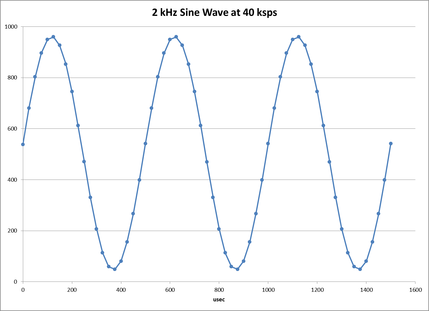
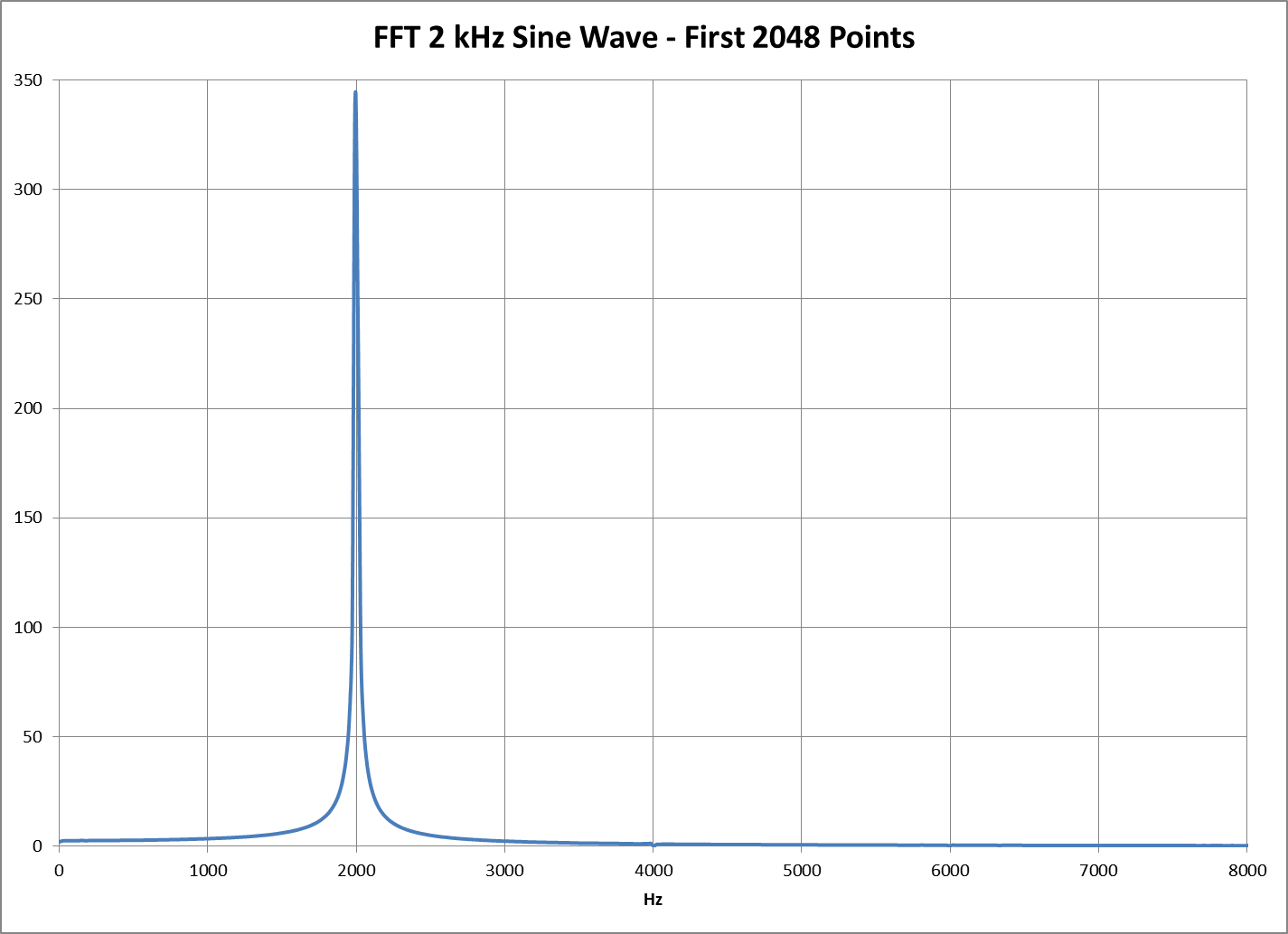
The attached file, DATA.png, is a plot of a 2 kHz sine wave logged at 40,000 samples per second. FFT.png shows a FFT of this data.

I did a reliability test logging five analog pins at 5,000 samples per second. This is an ADC rate of 25,000 values per second. I logged 512 MB of data without dropping any values.

Serial output from the test.

Sample pins: 0 1 2 3 4
ADC bits: 10
ADC clock kHz: 500
Sample Rate: 5000.00
Sample interval usec: 200.0000
Creating new file
Erasing all data
Logging - type any character to stop
Truncating file
File renamed: ANALOG10.BIN
Max block write usec: 920
Record time sec: 10239.992
Sample count: 51199950
Samples/sec: 5000.00
Overruns: 0
Done

Here is the first part of the csv file produced from the test by the included bintocvs program.

Interval,200.0000,usec
pin0,pin1,pin2,pin3,pin4
0,1023,0,670,0
0,1023,0,670,0
0,1023,0,670,0
0,1023,0,670,0
0,1023,0,670,0
0,1023,0,670,0

Pins 0, 2, 4 are connected to ground, pin 1 to 5V and pin 3 to 3.3V.

Here is the configuration section of the logger.

//------------------------------------------------------------------------------
// Analog pin number list for a sample.  Pins may be in any order and pin
// numbers can be repeated.
const uint8_t PIN_LIST[] = {0, 1, 2, 3, 4};
//------------------------------------------------------------------------------
// Sample rate in samples per second.
const float SAMPLE_RATE = 5000;  // Must be 0.25 or greater.

// The interval between samples in seconds, SAMPLE_INTERVAL, can be set to a
// constant instead of being calculated from SAMPLE_RATE.  SAMPLE_RATE is not
// used in the code below.  For example, setting SAMPLE_INTERVAL = 2.0e-4
// will result in a 200 microsecond sample interval.
const float SAMPLE_INTERVAL = 1.0/SAMPLE_RATE;

// Setting ROUND_SAMPLE_INTERVAL non-zero will cause the sample interval to
// be rounded to a a multiple of the ADC clock period and will reduce sample
// time jitter.
#define ROUND_SAMPLE_INTERVAL 1
//------------------------------------------------------------------------------
// ADC clock rate.
// The ADC clock rate is normally calculated from the pin count and sample
// interval.  The calculation attempts to use the lowest possible ADC clock
// rate.
//
// You can select an ADC clock rate by defining the symbol ADC_PRESCALER to
// one of these values.  You must choose an appropriate ADC clock rate for
// your sample interval. 
// #define ADC_PRESCALER 7 // F_CPU/128 125 kHz on an Uno
// #define ADC_PRESCALER 6 // F_CPU/64  250 kHz on an Uno
// #define ADC_PRESCALER 5 // F_CPU/32  500 kHz on an Uno
// #define ADC_PRESCALER 4 // F_CPU/16 1000 kHz on an Uno
// #define ADC_PRESCALER 3 // F_CPU/8  2000 kHz on an Uno (8-bit mode only)
//------------------------------------------------------------------------------
// Reference voltage.  See the processor data-sheet for reference details.
// uint8_t const ADC_REF = 0; // External Reference AREF pin.
uint8_t const ADC_REF = (1 << REFS0);  // Vcc Reference.
// uint8_t const ADC_REF = (1 << REFS1);  // Internal 1.1 (only 644 1284P Mega)
// uint8_t const ADC_REF = (1 << REFS1) | (1 << REFS0);  // Internal 1.1 or 2.56
//------------------------------------------------------------------------------
// File definitions.
//
// Maximum file size in blocks.
// The program creates a contiguous file with FILE_BLOCK_COUNT 512 byte blocks.
// This file is flash erased using special SD commands.  The file will be
// truncated if logging is stopped early.
const uint32_t FILE_BLOCK_COUNT = 256000;

// log file base name.  Must be six characters or less.
#define FILE_BASE_NAME "ANALOG"

// Set RECORD_EIGHT_BITS non-zero to only record the high 8-bits of the ADC.
#define RECORD_EIGHT_BITS 0
//------------------------------------------------------------------------------
// Pin definitions.
//
// Digital pin to indicate an error, set to -1 if not used.
// The led blinks for fatal errors. The led goes on solid for SD write
// overrun errors and logging continues.
const int8_t ERROR_LED_PIN = 3;

// SD chip select pin.
const uint8_t SD_CS_PIN = SS;

Hi, looks great! On which Arduino / using which shield did you make your measurements ?
Thx, Robert

I tested on an Uno and a Mega. The program is designed to work with other AVR boards.

To use other boards a section needs to add to this area to define BUFFER_BLOCK_COUNT and QUEUE_DIM.

#if defined(__AVR_ATmega328P__)
// 328 cpu -  use total of two 512 byte buffers
const uint8_t BUFFER_BLOCK_COUNT = 1;
// Dimension for queues of 512 byte SD blocks
const uint8_t QUEUE_DIM = 4;  // Must be a power of two!
//
#elif defined(__AVR_ATmega1280__) || defined(__AVR_ATmega2560__)
// Mega - use total of 13 512 byte buffers
const uint8_t BUFFER_BLOCK_COUNT = 12;
// Dimension for queues of 512 byte SD blocks
const uint8_t QUEUE_DIM = 16;  // Must be a power of two!
//
#else  // CPU types
#error Undefined CPU
#endif  // CPU types

I plan to use the RAMEND symbol to define these symbols in the next version.

I tested with a number of SD shields/modules.
You just need to edit this for your shield/module.

// SD chip select pin.
const uint8_t SD_CS_PIN = SS;

On Uno I mostly used an Adafruit data-logging shield. It has two LEDs and I used one for an error indicator.

// Digital pin to indicate an error, set to -1 if not used.
// The led blinks for fatal errors. The led goes on solid for SD write
// overrun errors and logging continues.
const int8_t ERROR_LED_PIN = 3;

I have updated the zip file attached to the first post to AnalogBinLogger20140326beta.zip.

I now determine the amount of buffering by use of the RAMEND symbol. This allows the logger to run on ATmega chips with 2 KB or more of SRAM.

I also fixed a problem that often causes an overrun due to SD write latency to be fatal.

I would appreciate any comments on results with various SD card. I have had the best luck with SanDisk class 4 cards.

This is the card I used in development http://www.amazon.com/dp/B007JRB0RY. I tested five of these cards, two 4 GB, two 8 GB, and one 32 GB. I have had almost no overrun errors on an Uno with these cards.

I have done some testing with this microSD http://www.amazon.com/Sandisk-MicroSDHC-Memory-Card-Adapter/dp/B000WH6H1M It appears to work but I have no done a long reliability test.

Here is the result of a short 100 MB session with the 8 GB class 4 SanDisk micro SD where the maximum write latency was 920 usec for a 512 byte block.

Sample pins: 0 1 2 3 4
ADC bits: 10
ADC clock kHz: 500
Sample Rate: 5000.00
Sample interval usec: 200.0000
Creating new file
Erasing all data
Logging - type any character to stop
Truncating file
File renamed: ANALOG01.BIN
Max block write usec: 920
Record time sec: 1993.845
Sample count: 9969226
Samples/sec: 5000.00
Overruns: 0

Here is one of the worst cards http://www.amazon.com/PNY-Optima-Class-Memory-P-SDHC4G4-EF/dp/B000L7INLU. I use it when I want to be sure of overruns.

Great results! I wish I had the SdFat (or Fat16/12) running on the 8MB Ramdisk :stuck_out_tongue:

I tried the AnalogBinlogger program (installed the library) and it won't compile on an UNO.
I changed the "SS" to 10 for my SD card chip select for my SEEED STUDIO SD CARD shield.
I have a 1 Mb Sandisk formated with SDFAT16. Attached is the verbose compiler output pasted into WORD.
I read the Readme file and didn't really see anything that looked like configuration instructions.
Can anybody tell me what I overlooked ?

COMPILE ERRORS.docx (15.6 KB)

bintocsv is a PC program not an Arduino library. Remove the bintocsv folder from Arduino libraries.

Thanks ! That eliminated the compile errors. I moved the bintocsv folder to my Arduino reference data folder. I assume I need to remove the SD card from my reader, plug it into my PC, open a command line and then execute the command line command:
bintocsv binFile csvFile ? What's the easiest way to do it ? Should I copy the bin file(s) from the SD card to the bintocsv folder and execute the command as you entered it or do I need a path for anything? (windows 7)

I tend to put the bintocsv.exe in the folder with the .BIN file.

You could also use a path to another location where bintocsv.exe is located.

Thanks. I'll do it your way.

Place the AnalogIsrLogger folder in your sketchbook folder.

I found this instruction in the readme file but didn't see any folder with that spelling . Is this important ?

Also, regarding these instructions:

You must edit the configuration constants at the beginning of the program
to set the sample pins, sample rate, and other configuration values.

Which file do I edit with my C++ editor ?

Initially the program is setup to log the first five analog pins at 5000
samples per second. Change these values to suit your needs.

See RateTable.txt for maximum allowed sample rates vs pin count and ADC clock
frequency.
The program has four commands:
c - convert file to CSV
d - dump data to Serial
e - overrun error details
r - record ADC data

I thought the bin to csv had to be performed using the command line instructions in the readme file .
So when you run the program it doesn't start recording (saving to SD) until you press "r" ?
The other two "d" & "e" make total sense.
Does the above mean I can perform any of those four commands after I start running the program ?

Place the AnalogIsrLogger folder in your sketchbook folder.

I found this instruction in the readme file but didn't see any folder with that spelling . Is this important ?

I should have just said sketchbook I guess. I didn't say the Arduino folder since you can select the folder to use.

The Arduino environment uses the concept of a sketchbook: a standard place to store your programs (or sketches). The sketches in your sketchbook can be opened from the File > Sketchbook menu or from the Open button on the toolbar. The first time you run the Arduino software, it will automatically create a directory for your sketchbook. You can view or change the location of the sketchbook location from with the Preferences dialog.

Which file do I edit with my C++ editor ?

You edit AnalogBinLogger.ino. for example to select the set of analog pins edit this area:

//------------------------------------------------------------------------------
// Analog pin number list for a sample.  Pins may be in any order and pin
// numbers may be repeated.
const uint8_t PIN_LIST[] = {0, 1, 2, 3, 4};
//------------------------------------------------------------------------------

Does the above mean I can perform any of those four commands after I start running the program ?

Yes just type the letter corresponding to the command you want run.

I thought the bin to csv had to be performed using the command line instructions in the readme file .

It takes a long time to convert large binary files on the Arduino so the PC/Mac command line program is often required.

THANKS !
I found it .

 //------------------------------------------------------------------------------
// Analog pin number list for a sample.  Pins may be in any order and pin
// numbers can be repeated.
const uint8_t PIN_LIST[] = {0, 1, 2, 3, 4};
//------------------------------------------------------------------------------
// Sample rate in samples per second.
const float SAMPLE_RATE = 5000;  // Must be 0.25 or greater.

// The interval between samples in seconds, SAMPLE_INTERVAL, can be set to a
// constant instead of being calculated from SAMPLE_RATE.  SAMPLE_RATE is not
// used in the code below.  For example, setting SAMPLE_INTERVAL = 2.0e-4
// will result in a 200 microsecond sample interval.
const float SAMPLE_INTERVAL = 1.0/SAMPLE_RATE;

// Setting ROUND_SAMPLE_INTERVAL non-zero will cause the sample interval to
// be rounded to a a multiple of the ADC clock period and will reduce sample
// time jitter.
#define ROUND_SAMPLE_INTERVAL 1
//------------------------------------------------------------------------------
// ADC clock rate.
// The ADC clock rate is normally calculated from the pin count and sample
// interval.  The calculation attempts to use the lowest possible ADC clock
// rate.
//
// You can select an ADC clock rate by defining the symbol ADC_PRESCALER to
// one of these values.  You must choose an appropriate ADC clock rate for
// your sample interval. 
// #define ADC_PRESCALER 7 // F_CPU/128 125 kHz on an Uno
// #define ADC_PRESCALER 6 // F_CPU/64  250 kHz on an Uno
// #define ADC_PRESCALER 5 // F_CPU/32  500 kHz on an Uno
// #define ADC_PRESCALER 4 // F_CPU/16 1000 kHz on an Uno
// #define ADC_PRESCALER 3 // F_CPU/8  2000 kHz on an Uno (8-bit mode only)
//------------------------------------------------------------------------------
// Reference voltage.  See the processor data-sheet for reference details.
// uint8_t const ADC_REF = 0; // External Reference AREF pin.
uint8_t const ADC_REF = (1 << REFS0);  // Vcc Reference.
// uint8_t const ADC_REF = (1 << REFS1);  // Internal 1.1 (only 644 1284P Mega)
// uint8_t const ADC_REF = (1 << REFS1) | (1 << REFS0);  // Internal 1.1 or 2.56
//------------------------------------------------------------------------------
// File definitions.
//
// Maximum file size in blocks.
// The program creates a contiguous file with FILE_BLOCK_COUNT 512 byte blocks.
// This file is flash erased using special SD commands.  The file will be
// truncated if logging is stopped early.
const uint32_t FILE_BLOCK_COUNT = 256000;

// log file base name.  Must be six characters or less.
#define FILE_BASE_NAME "ANALOG"

// Set RECORD_EIGHT_BITS non-zero to only record the high 8-bits of the ADC.
#define RECORD_EIGHT_BITS 0
//------------------------------------------------------------------------------
// Pin definitions.
//
// Digital pin to indicate an error, set to -1 if not used.
// The led blinks for fatal errors. The led goes on solid for SD write
// overrun errors and logging continues.
const int8_t ERROR_LED_PIN = 3;

I can't seem to get the program to run. It compiles fine but when I type in "r" in the serial port and hit enter, the error led
comes on and I get a "sample rate too fast" error
I attached the sketch renamed as MyAnalogBinLogger .
Can you help me configure it to sample A0 at 40,000 samples per second ?
I don't know what to select for ADC clock or SAMPLE_INTERVAL.

MyAnalogBinLogger.ino (23.7 KB)

Got it to work by changing the ADC clock rate to 1000 hz . What does 8-bit mode mean for the 2000 hZ clock rate ?
see attached

ANALOG00.CSV (537 KB)

MyAnalogBinLogger.ino (23.7 KB)

Can you help me configure it to sample A0 at 40,000 samples per second ?

First you need an SD card that has very low write latency.

I found this card works very well http://www.amazon.com/SanDisk-Class-Flash-Memory-SDSDB-004G-AFFP/dp/B007JRB0RY.

Change only these values.

//------------------------------------------------------------------------------
// Analog pin number list for a sample.  Pins may be in any order and pin
// numbers may be repeated.
const uint8_t PIN_LIST[] = {0};
//------------------------------------------------------------------------------
// Sample rate in samples per second.
const float SAMPLE_RATE = 40000;  // Must be 0.25 or greater.

Here is serial output for recording about five minutes of data. The proper SDHC card is extremely important.

Sample pins: 0
ADC bits: 10
ADC clock kHz: 1000
Sample Rate: 40000.00
Sample interval usec: 25.0000
Creating new file
Erasing all data
Logging - type any character to stop
Truncating file
File renamed: ANALOG01.BIN
Max block write usec: 1112
Record time sec: 304.766
Sample count: 12190600
Samples/sec: 39999.87
Overruns: 0
Done

What does 8-bit mode mean for the 2000 hZ clock rate ?

8-bit mode only records the high 8-bits of each ADC reading . At 2000 kHz ADC clock rate the ADC only provides about 7.5 significant bits. see the ADC_ENOB.PNG file. This reduces the amount of date written so it is easier for SD cards to handle the data rate.

I didn't include 8-bit mode in the max data rate table. Here is a version with 8-bit mode.

			ADC clock kHz		8-bit only
	125	250	500	1000		2000
pins						
1	7692	14286	25000	40000		57143
2	3810	6667	11111	16667		22222
3	2572	4790	8421	13559		19512
4	1942	3636	6452	10526		15385
5	1559	2930	5229	8602		12698
6	1303	2454	4396	7273		10811
7	1119	2111	3791	6299		9412
8	980	1852	3333	5556		8333
9	872	1649	2974	4969		7477
10	786	1487	2685	4494		6780
11	715	1354	2446	4103		6202
12	656	1242	2247	3774		5714
13	606	1148	2078	3493		5298
14	563	1067	1932	3252		4938
15	525	996	1806	3042		4624
16	493	935	1695	2857		4348

Here is serial monitor output for a short recording with an 18 microsecond sample interval.

Sample pins: 0
ADC bits: 8
ADC clock kHz: 2000
Sample Rate: 55555.55
Sample interval usec: 18.0000
Creating new file
Erasing all data
Logging - type any character to stop
Truncating file
File renamed: ANALOG02.BIN
Max block write usec: 1304
Record time sec: 28.103
Sample count: 1561189
Samples/sec: 55552.39
Overruns: 0

I am relatively new to arduino, but I am trying to get this code working on my Yun. I am trying to run your code as is, but I am getting a number of errors. Can you help clear up what I am doing wrong?

Arduino: 1.5.6-r2 (Windows 7), Board: "Arduino Yún"

AnalogBinLogger:143: error: 'SdFat' does not name a type
AnalogBinLogger:145: error: 'SdBaseFile' does not name a type
AnalogBinLogger.ino: In function 'void error_P(const char*)':
AnalogBinLogger:251: error: 'sd' was not declared in this scope
AnalogBinLogger.ino: In function 'void binaryToCsv()':
AnalogBinLogger:416: error: 'SdFile' was not declared in this scope
AnalogBinLogger:416: error: expected `;' before 'csvFile'
AnalogBinLogger:418: error: 'BufferedWriter' was not declared in this scope
AnalogBinLogger:418: error: expected `;' before 'bw'
AnalogBinLogger:420: error: 'binFile' was not declared in this scope
AnalogBinLogger:424: error: 'binFile' was not declared in this scope
AnalogBinLogger:430: error: 'csvFile' was not declared in this scope
AnalogBinLogger:430: error: 'O_WRITE' was not declared in this scope
AnalogBinLogger:430: error: 'O_CREAT' was not declared in this scope
AnalogBinLogger:430: error: 'O_TRUNC' was not declared in this scope
AnalogBinLogger:438: error: 'bw' was not declared in this scope
AnalogBinLogger:438: error: 'csvFile' was not declared in this scope
AnalogBinLogger.ino: In function 'void checkOverrun()':
AnalogBinLogger:497: error: 'binFile' was not declared in this scope
AnalogBinLogger:501: error: 'binFile' was not declared in this scope
AnalogBinLogger:504: error: 'binFile' was not declared in this scope
AnalogBinLogger.ino: In function 'void dumpData()':
AnalogBinLogger:538: error: 'binFile' was not declared in this scope
AnalogBinLogger:542: error: 'binFile' was not declared in this scope
AnalogBinLogger.ino: In function 'void logData()':
AnalogBinLogger:584: error: 'sd' was not declared in this scope
AnalogBinLogger:596: error: 'sd' was not declared in this scope
AnalogBinLogger:604: error: 'binFile' was not declared in this scope
AnalogBinLogger:605: error: 'sd' was not declared in this scope
AnalogBinLogger:614: error: 'sd' was not declared in this scope
AnalogBinLogger.ino: In function 'void setup()':
AnalogBinLogger:752: error: 'FreeRam' was not declared in this scope
AnalogBinLogger:755: error: 'sd' was not declared in this scope
AnalogBinLogger:755: error: 'SPI_FULL_SPEED' was not declared in this scope

  This report would have more information with
  "Show verbose output during compilation"
  enabled in File > Preferences.

Read Reply#5 & 6 on this post. Explains about where BIN2CSV program should be located. (can't be in same directory as library)

Hi,

I was wondering if this sketch can be used on a Teensy 3.1. did a quick test, however a few errors came up with respect to Too Little Ram and QUEUE_DIM, which is due to ram error not letting those be defined. If it is a easy fix to get this working on a teensy, that would be awesome. Thanks.

I was wondering if this sketch can be used on a Teensy 3.1 .... If it is a easy fix to get this working on a teensy, that would be awesome. Thanks.

The logger is closely associated with AVR so it would require a lot of mods.

I have no interest in porting this program to ARM since an RTOS based solution would be better on ARM.