Hey gang-
I need some help troubleshooting an LM317 constant current circuit (pcb) that isnt working (as I believed it should)..
well the pcb's came in.. and I assembled a couple..
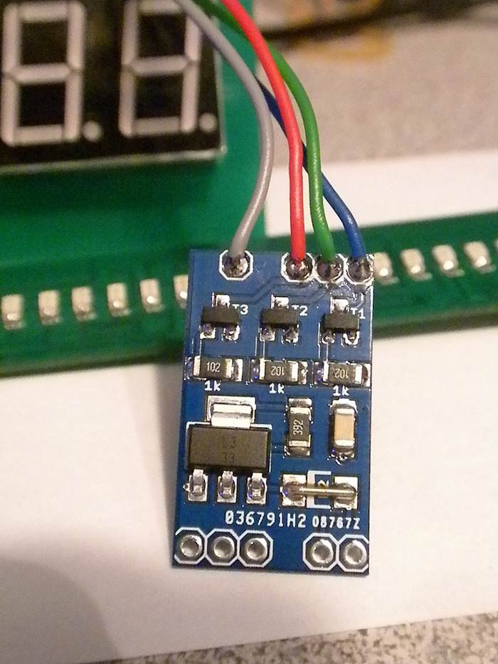
Here are the files schematic, board layout and a pic of the assembled board.
board:
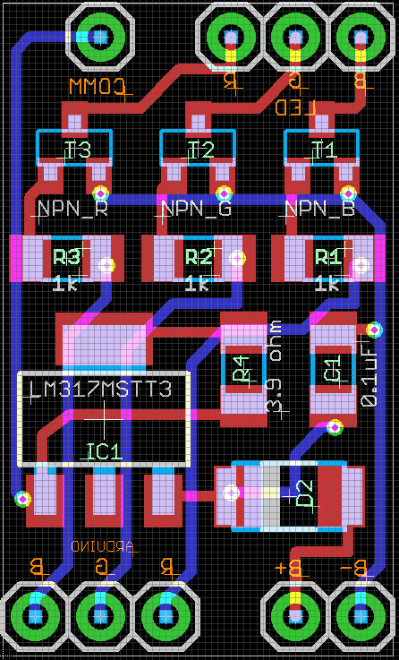
schematic:

and a pic of the assembled board:
before these boards came, I was using a simple Common Anode RGB led from RadioShack (not a high powered led, simple 20mA spec..etc)
I thought, when the board came... after being assembled and the 3Watt RGB LED star also connected... it would be a simple 'drop-in' replacement......(meaning just give the board the +7.4v directly from the battery source, and connect the 3 Arduino control/signal lines).... and it would be 'good to go'.. (so to speak)
however.. I obviously have made an error somewhere.. Im assuming on the board somewhere...
I dont mean physically during assembly, but in design perhaps? or maybe I'm missing things elsewhere on how this works? (I had posted the schematic/board for review while designing it)
I have taken the led wires.. connected it to my PSU (+3.3v/1A).. and tested the LED to ensure it IS common anode, does work, (is super bright)..and wasnt faulty there.
The transistors I'm using:
BC817: http://www.digikey.com/product-detail/en/BC81725MTF/BC81725MTFCT-ND/1305367
And the:
LM317: http://www.digikey.com/product-detail/en/LM317DCYR/296-12602-1-ND/443738
When connected.. it acts as if there is a short somewhere?
the led (RED) is ON...??
RGB in use,...the notoriously 'backwards' labeled DealExtreme 3W RGB star:
Where can I begin to troubleshoot this? (I'm hoping I dot need new boards for some reason?)
Im measuring +7.4v at the INPUT (which is right.. its from my PSU)
Im measuring roughly +6.72v on the OUTPUT (I removed the RGB LED and metered the plug/wires ends to get this)
sounds ok with voltage drop across the whole board/components? (but makes me worries since thats WAY over the vF of the RGB led I'm using)
not sure how to try and measure the current output?
nothings getting hot... (so thats good) LOL ![]()
thanks!