hello guys,
the schematic picture is in the attachment section
i have a question about it and i need your help:
why did we used another resistor which is the 27K and attached it to negative, isnt that the 33K enough to limit the current to the base of the PUT transistor ? or does it act like a voltage divider or something ?
second question why didn't we use a resistor on the output of the transistor to protect the LED because it's current is around 50mA?
in the second attachment file, i made the road of the current so i need please to know if it is right ?
Wow, that is a horribly drawn schematic. Is no one learning how to draw schematics any more? A large part of it is making them understandable. What website is that from?
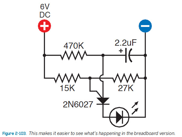
The break voltage of a PUT is set by the voltage on the gate. The 15k and 27k resistors are acting as a voltage divider, not a current limiter.
The 2.2uF capacitor charges slowly through the 470k resistor. When it reaches the programmed breakover point of the PUT, the PUT turns on and dumps the 2.2uF capacitor through the LED.
It isn't a PUT Transistor, it is a PUT because it is Programmable Unijunction Transistor.
You need to understand unijunction transistors to understand these circuits, they are
rather whacky devices - Unijunction transistor - Wikipedia
Basically there is a threshold voltage involved, the two resistors form a divider to program
the voltage. As the capacitor charges up the relative voltages change and at some point
the devices switches into conduction, draining the capacitor through the LED. The
resistance of the device itself is probably used to limit the current appropriately.
Since unijunction and prog. unijunction transistors have hysteresis the capacitor will
be discharged to well below the threshold and the cycle repeats.
I thought unijuction transistors were consigned to the history lessons these days to be honest!
polymorph:
Wow, that is a horribly drawn schematic. Is no one learning how to draw schematics any more? A large part of it is making them understandable. What website is that from?
polymorph:
Look here at page 3, figure 3 and you'll see the same circuit, with a 20 ohm resistor as a load where your circuit has an LED: Products and Technology | onsemi
well i don't see any LEDs, it's just one way to draw the transistor i guess
anyway ok so it's voltage divider but why is it needed here, is it that the base need just 5V or something ?
polymorph:
It isn't a PUT Transistor, it is a PUT because it is Programmable Unijunction Transistor.
As stated before, it is a programmable "device".
You set a value as reference, that's what's called programming here.
When the other input is at that programmed level, the transistor starts to conduct.
That other input is connected to a capacitor that is (slowly) charged by the 3rd resistor.
At the moment the transistor conducts, the capacitor is discharged through the LED.
This circuit will probably result in a LED that flashes (quite bright) for a short time and is off for some longer time.
If you want to control the charge speed by your Arduino, you can connect the + side of the charge resistor to an "analog" output instead of to that VCC.
If you want to control the programmable input, you need at least another capacitor to have a more realistic analog output instead of the PWM form the Arduino.
That capacitor should be part of the voltage divider.
As stated before, it is a programmable "device".
You set a value as reference, that's what's called programming here.
When the other input is at that programmed level, the transistor starts to conduct.
That other input is connected to a capacitor that is (slowly) charged by the 3rd resistor.
At the moment the transistor conducts, the capacitor is discharged through the LED.
ok great and what about the input from the 470K ? i mean we see the capacitor discharge threw the input, but we do have current passing from the + going into 470K then to input right ?
Yes, there would be some current flowing through the resistor and to the transistor while the transistor conducts.
But a resistance of 470K and a maximum of 6 volts, means a very low current.
Let's do some math:
U==I*R so I== U/R; 6 / 470000 == 0.0000128 (rounded).
That is 12.8 µA or 12.8 micro amperes, and without the LED in this equation (you need to subtract the forward voltage for that LED and the transistor, which would result in an even lower Amperage (some 7 µA)).
This will hardly be of any significance.
MAS3:
Yes, there would be some current flowing through the resistor and to the transistor while the transistor conducts.
But a resistance of 470K and a maximum of 6 volts, means a very low current.
Let's do some math:
U==I*R so I== U/R; 6 / 470000 == 0.0000128 (rounded).
That is 12.8 µA or 12.8 micro amperes, and without the LED in this equation (you need to subtract the forward voltage for that LED and the transistor, which would result in an even lower Amperage (some 7 µA)).
This will hardly be of any significance.
aha yea your right i didnt think about doing doing the math ! damn !
so yes the capacitor wins and it's the main source for the LED
Hi, do you have a specific reason for wanting to use the PUT?
Or is it just because it is part of the Make book exercises?
They are old technology and (sorry I'd say IT ,cos I don't think too many are manufactured now) I've only seen it used as an oscillator or SCR controller, all now done better with ICs.
the author of the book is drawing schematic like this for the purpose of learning
No he is doing it because iphe is a poor author who seems not to know any better. It is sad when you see such poor practice get past a technical editor and end up a waste of tree.
I used PUTs a lot in my first electronics job in 1967, however they were replaced by the more flexable NE555.
Grumpy_Mike:
No he is doing it because iphe is a poor author who seems not to know any better. It is sad when you see such poor practice get past a technical editor and end up a waste of tree.
I used PUTs a lot in my first electronics job in 1967, however they were replaced by the more flexable NE555.
why ? but he said it before he explained all the method of doing schematic and many symbols how to do it and where and then he chose one and said i will continue with this to be clear, and about old stuff he explained 2
which book do you suggest if i would love to go pro ?
i started with this book because it seemed easy and not demanding lots of time, got few other options but i would love to get ur advise about a book that if i read it right and do the experience in it, i can be able to understand and design circuits in a good way so what's you suggestion ?
I don't have a dog in this fight, but a couple of questions:
The original schematic:
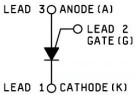
That isn't a PUT. It is an SCR symbol.
The PUT symbol is shown on the supplied link (page 3) as other transistors, which also have the SCR in them.
What am I missing?
i don't know why did he used this symbol but what i know for now that i am actually gaining something from reading this book and after i finish will do something a bit "better" and more pro, and that way i will be more into it, same case when i started with arduino and having less than 1% of knowledge about electronics, now it's 1%+
he said it for learning purpose he made the simplest way and it is understandable for a beginner or amateur ! well to me at this stage i can understand these schematic in more easy way than schematic in the first link
i can turn it the other way lol
he said it for learning purpose he made the simplest way and it is understandable for a beginner or amateur
He might but he is very much mistaken.
Basically current should flow from top to bottom and signals should be inputs on the left and output on the right.
He is making current flow from left to right.
I don't know why you find that easier to follow but when you grow up you will have to learn the proper way and if you have first learned something wrong it is very much harder for you to learn the right way.
This has been shown over an over again. For example there was the ITA way of spelling that crippled the spelling skills of a whole generation of children. Initial Teaching Alphabet - Wikipedia.
Also you do here of music teachers that struggle for years to get students out of early learned bad habits.
So a bit of advice, junk that book it is doing you harm.