So I bought a 3.7V LiPo battery and uploaded my code
#include "FastLED.h"
// Fastled constants
#define DATA_PIN    2
#define COLOR_ORDER GRB
#define NUM_LEDS    16
#define LED_TYPE    WS2812B
#define BRIGHTNESS  64
CRGB leds[NUM_LEDS];

#define LED_PIN 1  // Built in LED

void setup() {
  FastLED.addLeds<LED_TYPE, DATA_PIN, COLOR_ORDER>(leds, NUM_LEDS);
  FastLED.setCorrection( TypicalLEDStrip );
  FastLED.setBrightness( BRIGHTNESS );
  FastLED.clear();
  pinMode(LED_PIN, OUTPUT);
}

void loop() {
  anim1();
}

void anim1() {
  fill_solid (leds, NUM_LEDS, CRGB::Red);
  FastLED.show();
  digitalWrite(LED_PIN, LOW);  //  Turn the LED on
  delay(200);
  fill_solid (leds, NUM_LEDS, CRGB::Blue);
  FastLED.show();
  delay(200);
  fill_solid (leds, NUM_LEDS, CRGB::Green);
  FastLED.show();
  digitalWrite(LED_PIN, HIGH); //  Turn the LED off
  delay(200);
  fill_solid (leds, NUM_LEDS, CRGB::White);
  FastLED.show();
  delay(200);
}
When I plug the ESP on the module and supply it, I see the blue builtin LED lit but the ring doesn't work.
I know that WS2812 require 5V supply, the battery provides 4.22V when full, so it should be ok. Also, the ESP data pin can only output 3.3V, and the LEDs require 5V data voltage.
BUT ! the seller's website shows a video with the ring working!
Has anyone any experience with this LED control module, and can anyone help me have this stuff work?
Thanks for your help
Ah, sorry. It's some example code posted in a customer review. And unfortunately it's an image, so you can't paste it into the IDE. It uses the AdaFruit library, not fastLED, but the review implies that it works well. You may have to type the code in. Perhaps you can Google for a line of the code.
Thanks, I have seen this code and copied it : nothing happens.
The ESP01 is OK, I had the blue builtin LED flashing. I wonder if it's coming from the LED ring which needs 5V on the data pin. And the ESP01 can only provide 3.3V. I expected the control module to take care of that...
Anyways, the seller managed to have it work, that's what amazes me!
Eureka : it was a connection problem. Now it works with one ring. 16 LEDs.
I cascaded 2 rings but only the 21 first LEDs light up. I believe it's because the current output by the GPIO02 is not high enough to reach the 22nd LED and after.
Can anybody help and suggest a simple current amplification module or circuit ? I need only +50% amplification (from 21st to 32nd LED). The supply is from a LiPo battery 3.7V 380mAh.
Thanks for your help
No, that is definitely not the reason. Each led in the ring buffers the signal to the next led on the ring (or the second ring). The gpio pin only has to supply the first led. The current required to do this is very small.
Can you swap over the two rings? How many leds light up? Is it 5?
I can't swap, they are soldered.
16 + 5 on the second ring are lit. But sometimes, the whole second ring lights up, but the other 11 stay lit and don(t do the next animation.
I must add that there is roughly 1 meter long cables (VCC, GDN, data) between the controler and the first ring. The second ring is very close to the first one.
My best guess is that you have faulty led in the second ring. I would un-solder and swap the rings.. Then, if only 5 on one ring light and nothing on the second, it's a faulty led. But if there is no change, then must be some other problem.
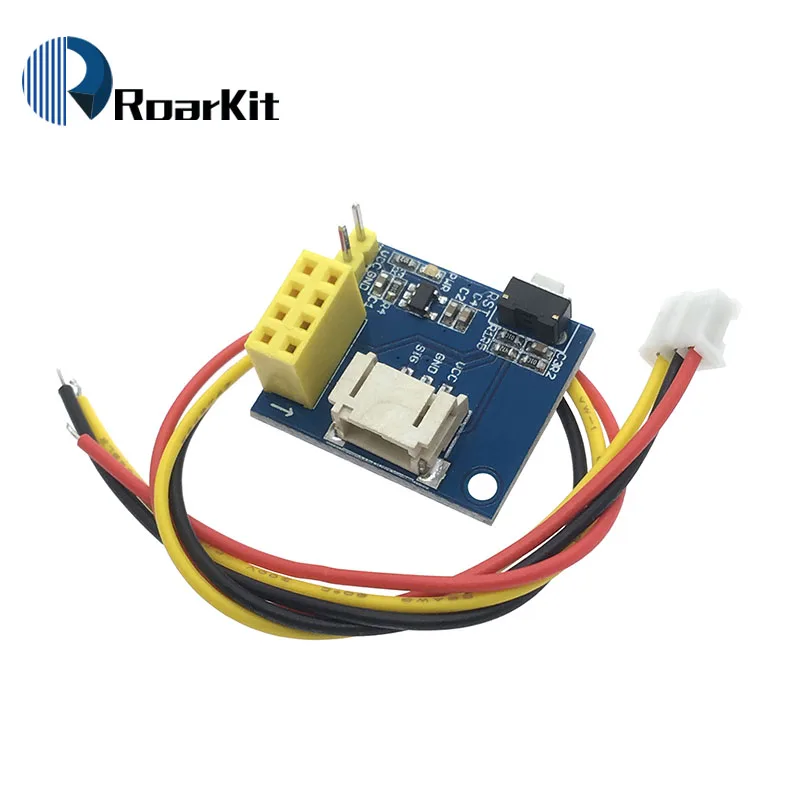
I just hooked up an ESP-01 to a 4x4 Neopixel matrix and 8-led ring, running the above code, and it works perfectly all by itself. So I'm a little mystified about what the LED controller pictured here actually does.
It looks like it has a 3.3V regulator for the esp, and suitable socket that matches the plug some strips are supplied with. Apart from that, not much, I would say. I suspect it might work with some ws2812b strips, I have had success connecting esp to those. But I found that with ws2811 strips/strings, a 3.3V-5V level convertor is needed, so without that, the module might not work.
It does exactly what you see on the board - it has a reset switch for no particularly obvious reason except "it can", a 3.3 V regulator to supply the ESP-01 and the necessary connections between the pinouts and sockets.
I just happened on these on eBay. I was about to order some to work with the ESP-01 and WS2812 pixels running on 5v and controlled via WiFi from a Laptop running Vixen software.
Are they any good?
Be warned that the NeoPixels may or may not work when driven with 3.3. V logic. You probably should include a 74HC14 level converter - two of the inverter gates cascaded to cancel the inversion - in the data line.
DougLeary:
I just hooked up an ESP-01 to a 4x4 Neopixel matrix and 8-led ring, running the above code, and it works perfectly all by itself. So I'm a little mystified about what the LED controller pictured here actually does.
I was just playing with one off of Aliexpress (for $6.50 I'm like "sure"), and this one and a similar DHT11 board I got look almost identical. Identical in size, and the side with the power pins and reset button has all the same components, only lacking a single resistor. Maybe someone's building an ecosystem?
Feeding it 5v, I'm seeing 3.3v on the ESP, so the board is doing something.