I have formed this dimming circuit(attached) on the basis of the following circuit:
but the bulb will not power up, i think it's not getting the other point that is neutral and the MT1 and MT2 of both the BTA10 and BTA12 are same as i checked the datasheet for it plus other connections seem to be fine too.
please suggest a remedy?
I hve tested to know that LED is working but the MOC and triac aren't working till now
help things are getting sparky
i did this with Christmas lights(resistive load unlike yours) and used the first scheme attached. but i also had the second scheme for something like your trying to do.
Actually im facing problem mainly at triac end with not correct connection of bulb ,so im going to use schema 1 of yours
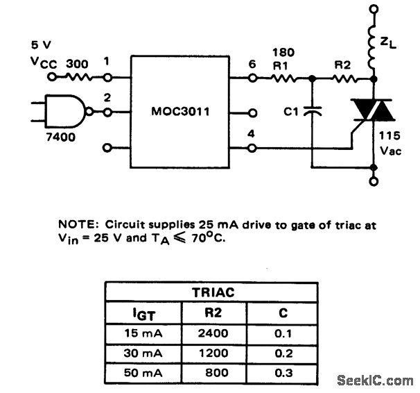
an inductive load does change the MOC and TRIAC scheme: http://www.seekic.com/uploadfile/ic-circuit/200972152114212.gif
At this time im doing the same circuit but it isnt working for me yet
EDIT:
Attached you will find the Bread board connections(dn't be shocked by the tin wires running im duely taking care :D)
Triac Blown and Fireworks were there


