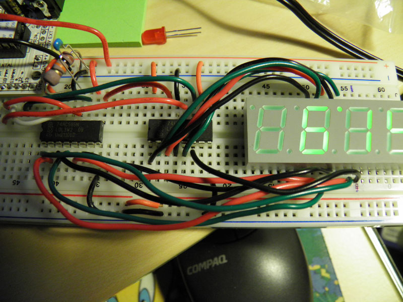
By arranging the shift registers adjacent to the LED it was possible to keep wiring to a minimum. So you only need 3 wires (MOSI, SS, SCK) from the Arduino to the board (plus 5V and Gnd).
The actual displaying is done by a timer interrupt routine, so you can be doing other things in your sketch while the display is updated automatically. The whole thing is quite cheap, the registers are under a $1 each, and the LED was about $3.
It would be possible to add another LED with another two shift registers (I've put a dot on the board where pin 1 would go) so as to extend the number of digits to 8.
(edit) As discussed further down this thread, current limiting resistors would be advisable for the health of the LEDs and ICs. (April 2012).
I decided not to use resistors in the end, "live recklessly", I thought.
If it looked too bright I was going to unplug it quickly. A quick check with the logic analyzer seemed to show that the SPI data was being clocked out at about the right rate. In fact, it was far too slow, with the segments lighting up briefly and then with a lengthy pause between them.
I did some tweaking "by eye" to get the segments to look "not too bright" but not flicker either.
This is what it looks like:
There is a slight flicker, you can eliminate that by increasing the interrupt fire rate. ie. change:
OCR2A = 124; // count up to 125 (zero relative!!!!)
Well the theory is that you are delivering higher current than it should get, for less time. So the average is OK. The Lots Of Leds shield, for example, doesn't have resistors.
Measurement appears to indicate that a particular segment is on for 4 mS and off for 17 mS (depending on what you are displaying of course) so that is 4/23 "on" duty cycle, or 17%.
There is a limit to how much the chip can deliver (say, 40 mA) so we are on average supplying 17% of 40 mA, namely 6.8 mA.
I can't find a definitive proof of this, maybe the electronics engineers here might like to comment?
I think the problem place is really the "sink" pins, because they would have a duty cycle of 25% (as they rotate from digit to digit). However I built in a "blanking" period of 8 cycles (8 mS) when all the pins are held low, and thus won't conduct anything. So they, too, should get a rest.
If you greatly increase the blanking time, eg.
const byte TIME_BETWEEN_DIGITS = 100; // blanking period between digits in loop iterations
... and then make the timer fire faster to remove flicker:
OCR2A = 9; // count up to 10 (zero relative!!!!)
... then the LEDs are noticeably dimmer (but still readable) and there is no noticeable flicker (although I do notice a slight flicker every 10th of a second which is when interrupts are turned off to update the counter).
There is a limit to how much the chip can deliver (say, 40 mA) so we are on average supplying 17% of 40 mA, namely 6.8 mA.
I can't find a definitive proof of this, maybe the electronics engineers here might like to comment?
See, that's what I want to know. As far as I'm aware, the 74HC595 has an absolute maximum rating of 35mA per output pin. But that doesn't mean it will stop when it hits 35mA. That just means if you try to draw more than that you'll fry it. I think the actual amount of current it will output would be limited only by whatever resistance there is in the chips, wire, and battery, and that would be fairly small.
Have you tried connecting a multimeter up to see how much current it says is flowing through any particular pin or led? Maybe measure the sink side that is at a 25% duty cycle to get the most accurate measurement?
I guess if the leds aren't really bright then the amount of current must be being limited somehow. The question is whether it is below the maximum ratings of the chip per output and for the whole chip. Even a 17% duty cycle would explode the leds if the chip was drawing 500mA.
Right, well it's a bit hard to measure because the output pins are soldered directly to the tracks on the PCB.
But to try to get an idea, I broke the wire leading to the entire 74HC595 chip's Vcc pin, and measured the current on that. Presumably no output pin will source more current than the chip itself consumes.
On the original sketch I measured:
Peak current:      38.6 mA
Average current:   14.5 mA
With the modified sketch I mentioned (where the LEDs were dimmer because of a lower duty cycle) I got:
Peak current:      38.6 mA
Average current:    2.5 mA
So we seem to be in the reasonably safe ballpark. Even the peak current seems to be acceptable (assuming you can average it over a few pins), and that would only be at that level for a couple of milliseconds before the blanking period cut in.
I have been playing with a similiar subject... and I too have found this a nice neat solution, with an added bonus... the led display becomes a sort of indicator.. as long as you can see more than one digit, the code is running as a result, i dont bother with heartbeat leds when I use this solution.
I decided not to use resistors in the end, "live recklessly", I thought. smiley
I am using common anode leds so i went with resistors, but with common cathode why not?
Surely for common anode, resistors are a bit more important?
I only ask as my understanding is, that the current will see path of least resistance and may accelerate degredation of the segments, or uneven illumination as each digit only has one source.
with common cathode, you dont have this problem as each segment is sourced individually.
Huh? I'll let my electronics experts friends respond to that, but as far as I am aware, it's just like turning an LED around. Providing you also turn the current around "the other way" it should be the same.
I have it wired up (not exactly like your diagram) and segments displaying OK (at least I can see them working - of course all 4 digits show the same thing right now), although I haven't figured out the common cathode pins yet.
I have a newbie question which I have not seen asked - how do you manage to show the individual digits without using transistors? Bear with me - I've been reading all I can for a week in this subject, and everything else I see uses a transistor hooked up the each of the common cath pins to display each digit in multiplexing.
The shift register can source and sink a bit of current (something like 20 mA) and by multiplexing it is only doing a segment at a time (or thereabouts).
So basically rather than using a transistor to boost the current output, and then a resistor to limit it again (because the LEDs don't need that much) the simpler system is just to briefly send a bit of current to each LED.
Thanks sir! Here is my (drum roll) implementation of your circuity on a breadboard! Thanks for your inspiration and help! I used your coding with some minor modifications. This is my first 7Seg LED, and first usage of shift registers. BTW - I did have 220 ohm resistors hooked up in series from the shift registers to each segment in the display to begin with, but I removed all of them to try out your method.
Well the theory is that you are delivering higher current than it should get, for less time. So the average is OK.
Nick, no, no no.
It is the peak current that is important not the average current when considering component ratings. Have you not read my page:- http://www.thebox.myzen.co.uk/Tutorial/LEDs.html
The Lots Of Leds shield, for example, doesn't have resistors.
So that makes it OK then? Or does it make it yet another circuit designed to destroy components?
Very informative page, thanks Mike. I did some research before but didn't find that particular page.
I had seen some references to putting high currents into LEDs (eg. IR transmitters) for a brief time, but on careful reading it appears that such LEDs would be designed to handle that, and in any case, the higher current does shorten their life, it's just allowed for in the design.
So would you say then that 8 resistors, in series with A-G/DP would be the best? Or 4 in series with each of the digits? I'm guessing that the 8 are better because that would give more even current.
So that makes it OK then? Or does it make it yet another circuit designed to destroy components?
Forgive me, but I assumed that a commercially sold board would have investigated the ramifications of this and found out that the design was OK.
The problem with that is as more segments come on more current is drawn therefore more voltage is dropped across the resistor. That means that the digit's brightness depends on the number of segments that are on. So you get a bright 1 and a dim 8. The resistors need to be in each segment so 8 it is. That is the attraction of having constant current drives.
I had seen some references to putting high currents into LEDs
Yes a lot of LEDs have a pulse current specification that is much higher than the continuous current rating. The on / off ratio is normally quoted and it is used to compensate, to some extent, for the dimming caused by the on / off ratio. However, even so the current has to be managed to be within that specification, and it does shorten the life. A firm I worked for had a 10% return rate on set top boxes with high current pulsed LEDs even though the current was within the specification. Contracts often mention a epidemic failure clause that kick in at about 3% so there was a lot of fuss about that. When making a million boxes 10% is a lot. There were 19 LEDs on the box and it only takes one to fail for the box to fail, that is be returned.
However, the major problem with high pulsed currents is from the driver rather than the LED. The potential for doing damage is a lot greater because chips are of a physically more delicate construction than LEDs.
but I assumed that a commercially sold board would have investigated the ramifications of this and found out that the design was OK.
Ah if only that were true. Thing is, even commercial designs are made by people, with all the variability that implies. You should have seen some of the things I had to correct from my 'professional' engineers when I was a manager.
The Sparkfun serial LED displays have taken this route I think, you can't see all the PCB so I can't verify how many resistors (if any) have been used but the brightness varies a lot depending on the number of segments lit.
Grumpy_Mike:
The problem with that is as more segments come on more current is drawn therefore more voltage is dropped across the resistor. That means that the digit's brightness depends on the number of segments that are on. So you get a bright 1 and a dim 8. The resistors need to be in each segment so 8 it is.
I guessed that would be the case, .
In my alarm clock circuit here:
I used 4 resistors. And guess what, the digits were varying brightness depending on how many segments lit up. Ah well, we live and learn.
Thing is, even commercial designs are made by people, with all the variability that implies
I think I am beginning to understand why my electric blankets have been failing every year. They have pretty sophisticated-looking control boxes, but don't seem to last very long. Either they are badly designed, built to a (low) price, or both.
Either they are badly designed, built to a (low) price, or both.
In the battle of conspiracy over cockup, I vote for cockup every time.
Most things are built to a price coupled with a reliability target. It is the target reliability that drives most consumer goods in large companies, mainly because return figures are easy to collect as a metric. No prizes are given for over achieving on reliability, in fact in most cases you are criticised for not making it cheap enough. In fact in my last job that was written into our contracts.