MartinL:
Hi vortix2950,In rate mode the sticks will act in the same way as an aeroplane joystick, in that the further from centre that the stick is moved on a given axis, the faster the aircraft rotates. Centring the stick will cause the aircraft to stop rotating on that axis.
Imagine a jet fighter flying straight and level, to fly inverted the pilot pulls hard right on the joystick to roll the aircraft, then immediately centres the stick once he/she has reached the inverted position. With the stick centred the fighter continues to fly up-side-down in the inverted position. It's the same in rate mode.
In your program you need to first calibrate your gyroscope in the setup() portion of your code. This is achieved successively adding say a hundred or so samples for each of the the gyroscope's axes then dividing by the number of samples, to calculate the mean average:
// Acquire the aircraft's current rate over a number of samples
// This information is used to calibrate the gyro
for (int i = 0; i < SAMPLE_NO; i++)
{
accelgyro.getRotation(&gx, &gy, &gz);
baseGx += gx;
baseGy += gy;
baseGz += gz;
}
// Divide by the number of samples to find the starting base point for the gyro
baseGx /= SAMPLE_NO;
baseGy /= SAMPLE_NO;
baseGz /= SAMPLE_NO;
To calculate the gyroscope output in terms of degrees per second, (assuming that's the units you're using?), it's first necessary to determine the full scale rotation (±250°/s, ±500°/s, ±1000°/s, ±°2000/s), again during setup():// #define MPU6050_GYRO_FS_250 0x00
// #define MPU6050_GYRO_FS_500 0x01
// #define MPU6050_GYRO_FS_1000 0x02
// #define MPU6050_GYRO_FS_2000 0x03
accelgyro.setFullScaleGyroRange(MPU6050_GYRO_FS_500);Then use this information to convert the raw gyroscope output to degrees per second in the loop() portion of your sketch:// Convert raw gyro output to degress per second
//const float FS_SEL = 133.0; // Gyro +-250 degrees/s
const float FS_SEL = 66.0; // Gyro +-500 degrees/s
//const float FS_SEL = 33.0; // Gyro +- 1000 degrees/s
//const float FS_SEL = 16.0; // Gyro +- 2000 degrees/s
float gyroRollRate = (float)((gy - baseGy) / FS_SEL);
float gyroPitchRate = (float)((gx - baseGx) / FS_SEL);
float gyroYawRate = (float)((gz - baseGz) / FS_SEL);Your axes assignment may differ depending on the orientation of the gyroscope on your flight controller board. The gyroscope output in degrees per second can be used as the "input" to your roll, pitch and yaw PID control loops, while the pilot stick inputs, also converted to degrees per second, is the "setpoint".
I had my Gyro Set to 250 and is divided by 131. switched to the 500/s but no difference. it looks fine as you increase throttle, but it just topples once it starts taking off.
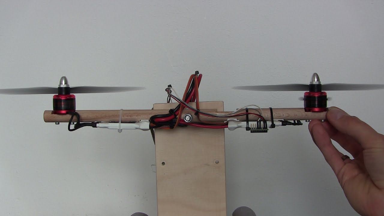
my Pid does what you described but doesnt seem to work. i pretty much followed along with this video for Pid
:
moving the quad to any direction gives correct response when it comes to motor mixing. but still, no PID combination seems to give anything resembling flight.
here is the Code again :
Servo ESC;
Servo ESC2;
Servo ESC3;
Servo ESC4;


float Porpotional_gain=0.2;
float Integral_gain=0;
float Derivative_gain=0.0;

float Porpotional_gain_y=0.1;
float Integral_gain_y=0.0;
float Derivative_gain_y=0;

MPU6050 mpu;

MPU6050 accelgyro;


int16_t ax, ay, az;
int16_t gx, gy, gz;

setup(){

    mpu.setXGyroOffset(81);
    mpu.setYGyroOffset(13);
    mpu.setZGyroOffset(-10);
    mpu.setZAccelOffset(16394);


 ESC.attach(Motor1ESC , 1000 , 2000); //3
 ESC2.attach(Motor2ESC , 1000 , 2000);//
 ESC3.attach(Motor3ESC , 1000 , 2000);
  ESC4.attach(Motor4ESC , 1000 , 2000);


}

Loop(){

    accelgyro.setFullScaleGyroRange(MPU6050_GYRO_FS_500);
    accelgyro.setDLPFMode(MPU6050_DLPF_BW_20);
    accelgyro.getRotation(&gx, &gy, &gz);

    gx=(gx/66.0);
    gy=(gy/66.0);
    gz=(gz/66.0);

    CurrentReading_Yaw=gz;
    CurrentReading_Roll=gx;
    CurrentReading_Pitch=gy;

   Desired_Roll=RCx;
   Desired_Pitch=RCy;
   Desired_Yaw=RCz;

    Error_Pitch=Desired_Pitch-CurrentReading_Pitch;
    Error_Roll=Desired_Roll-CurrentReading_Roll;
    Error_Yaw=Desired_Yaw-CurrentReading_Yaw;

    Integral_Pitch+=Integral_gain*Error_Pitch;
    Integral_Roll+=Integral_gain*Error_Roll;
    Integral_Yaw+=Integral_gain_y*Error_Yaw;

    Derivative_Roll=Derivative_gain* (Error_Roll-Prev_Error_Roll);
    Derivative_Pitch=Derivative_gain* (Error_Pitch-Prev_Error_Pitch);
    Derivative_Yaw=Derivative_gain_y* (Error_Yaw-Prev_Error_Yaw);

    Input_Pitch=(Porpotional_gain*Error_Pitch)+Integral_Pitch+Derivative_Pitch;
    Input_Roll=(Porpotional_gain*Error_Roll)+Integral_Roll+Derivative_Roll;
    Input_Yaw=(Porpotional_gain_y*Error_Yaw)+Integral_Yaw+Derivative_Yaw;

if(Input_Pitch>200){Input_Pitch=200;}
if(Input_Roll>200){Input_Roll=200;}
if(Input_Yaw>200){Input_Yaw=200;}

if(Input_Pitch<-200){Input_Pitch=-200;}
if(Input_Roll<-200){Input_Roll=-200;}
if(Input_Yaw<-200){Input_Yaw=-200;}


    Motor_1_Speed=(MotorPower_Throttle)+Input_Roll+Input_Pitch+Input_Yaw;//+
    Motor_3_Speed=(MotorPower_Throttle)-Input_Roll+Input_Pitch-Input_Yaw;//-
    Motor_2_Speed=(MotorPower_Throttle)-Input_Roll-Input_Pitch+Input_Yaw;//+
    Motor_4_Speed=(MotorPower_Throttle) +Input_Roll-Input_Pitch-Input_Yaw;//-


   ESC.writeMicroseconds(Motor_1_Speed);
   ESC2.writeMicroseconds(Motor_2_Speed);
   ESC3.writeMicroseconds(Motor_3_Speed);
   ESC4.writeMicroseconds(Motor_4_Speed);


}
Loop is limited to 4ms by a timer so no need to use a time error in the Pid. The "desired" values are the setpoint from the transmitter and they range from -45 to 45. this should work as a rate controller from all the sources i have seen including the video linked but it doesn't.
The quad im using is a small 90mm if that matters.
