does anyone got experienced using microstep driver type that requires 5v high and 0v low....i measure my arduino using multimeter i didnt reach 5v but just approximately 3v when high....anybody know a proper way to generate 5v output properly
from arduino pin....
If your stepper motor is suitable, the Pololu A4988 stepper motor driver board can be set to do various levels of microstepping. It connects directly to the Arduino and can use a motor power supply of up to 30v or so.
You can't power the motor from an Arduino - it can't produce enough current. If you try you will damage the Arduino.
...R
zamir89:
does anyone got experienced using microstep driver type that requires 5v high and 0v low....i measure my arduino using multimeter i didnt reach 5v but just approximately 3v when high....anybody know a proper way to generate 5v output properly
from arduino pin....
pinMode (pin, OUTPUT) ?
digitalWrite (pin3, HIGH);
delay (pulseWidth);
digitalWrite (pin3, low);
delay (pulseWidth);
what is the usual frequency or input to activate this type of driver
ims200.pdf (228 KB)
Stepper drives with step/direction inputs normally specify a minimum 10us pulse width
(this is for slow opto-couplers). The setup time for direction is usually smaller.
Thus the typical driver code is
void step (boolean direction)
{
  digitalWrite (dirPin, direction) ;
  delayMicroseconds (2) ;  // only needed on fast boards like Due
  digitalWrite (stepPin, HIGH) ;
  delayMicroseconds (10) ;
  digitalWrite (stepPin, LOW) ;
}
Some stepper libraries already support step/direction drivers (I think AccelStepper does).
btw im using arduino uno.....is the driver requires 5v on 0v off input to turn it on how does i measure it output using multimeter
Why do you think you need to measure the voltage. An Uno sets it's output pins to 5v or 0v (assuming you have used pinMode(pinNumber, OUTPUT).
A multimeter will only read the voltage properly if the pin is unchanged for several seconds.
What stepper driver are you using? Please post a link to it's specifications.
...R
here i attached the datasheet ......well i has try many code in it but the motor still no response.... maybe because of the arduino code or the driver it self....i read at some forums this type of driver need a proper frequency input to make it function that why i want to measure the arduino output
ims200.pdf (228 KB)
That driver seems to have an unusual input signal. It seems that it requires pulses on one pin to drive in one direction and pulses on the other pin to drive in the other direction (5. Connection Diagram).
It also seems that one of each pair of step pins needs to be connected to the Arduino 5v pin. Presumably, then, a step arises when the step pin goes low. Also I presume that the non-driving side (CCW if you are driving CW) should be high.
If that is correct it should be very easy to control.
It seems to be essential to power it with a 24v power supply (+/- 10% is stated). Have you got a 24v supply?
...R
No, don't do that, set jumpers JP1 and JP2 to do "pulse setting (clk/dir)", so that
its like every other stepper driver on the planet and relevant libraries support it.
The inputs are just opto couplers, no need to connect to +5, you can connect
cathode side to GND and anode to a pin.
MarkT:
No, don't do that, set jumpers JP1 and JP2 to do "pulse setting (clk/dir)",
Ah... I didn't read that far ...
...R
errr sir....can i know where should i put for pulse and dir pin for the + and -
Each '-' input goes to GND, each '+' input to the relevant Arduino pin, which
needs to be an OUTPUT pin.
Then when the Arduino pin is HIGH the opto-coupler will be activated for that pin.
You could also add an LED and 1k resistor to the pin to show you what state it is
if you want to see what's happening.
the motor still wont move :(....should i change the currnet jumper setting to 1.2amp cause i dont know my motor spec
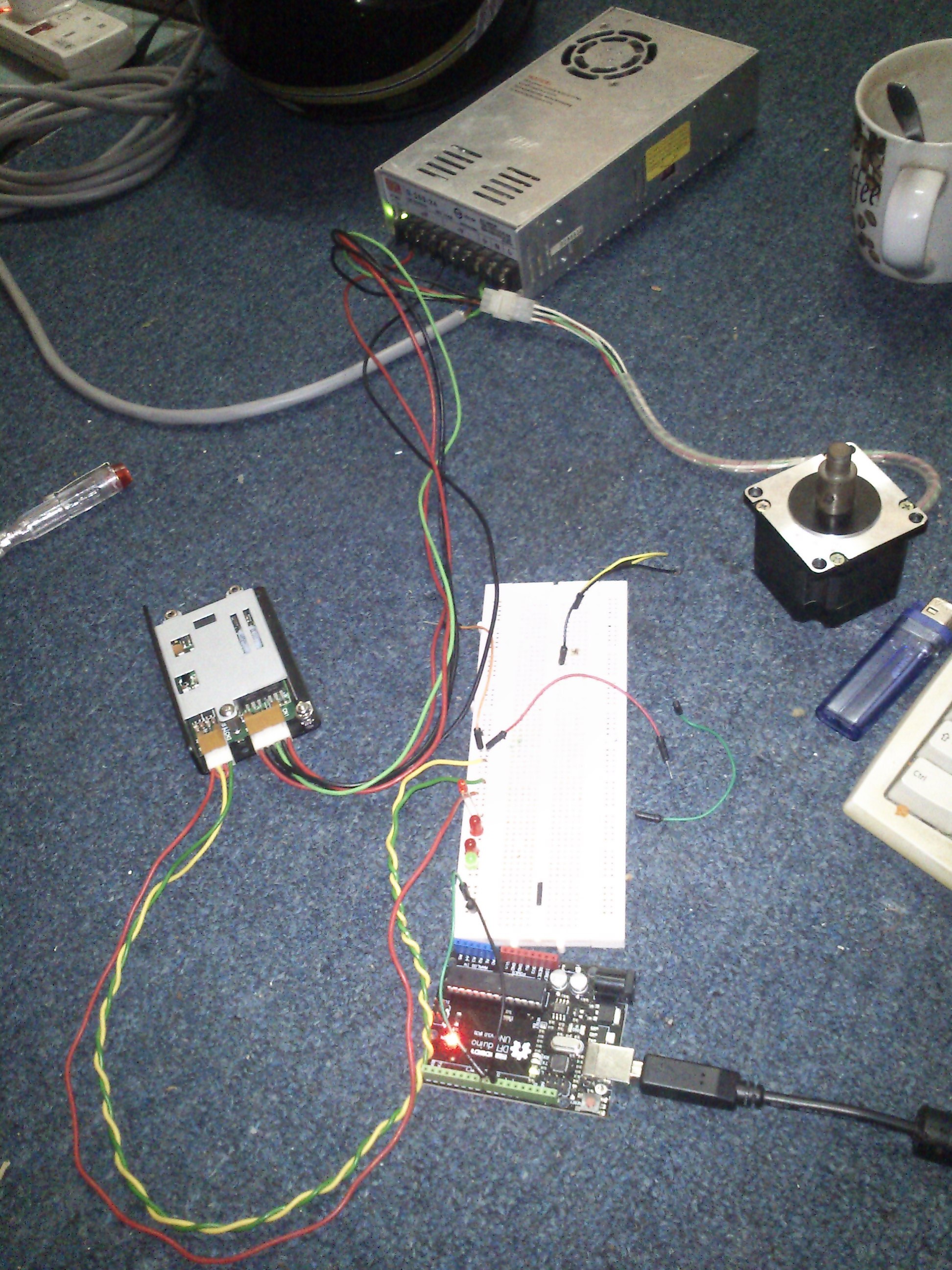
I can't work out from your photo where exactly each connection goes. Please make a clear drawing of exactly how everything is connected and post a photo of the drawing.
...R