So I've been banging my head against this for a few days and I have come to the conclusion that my Arduino is dead.
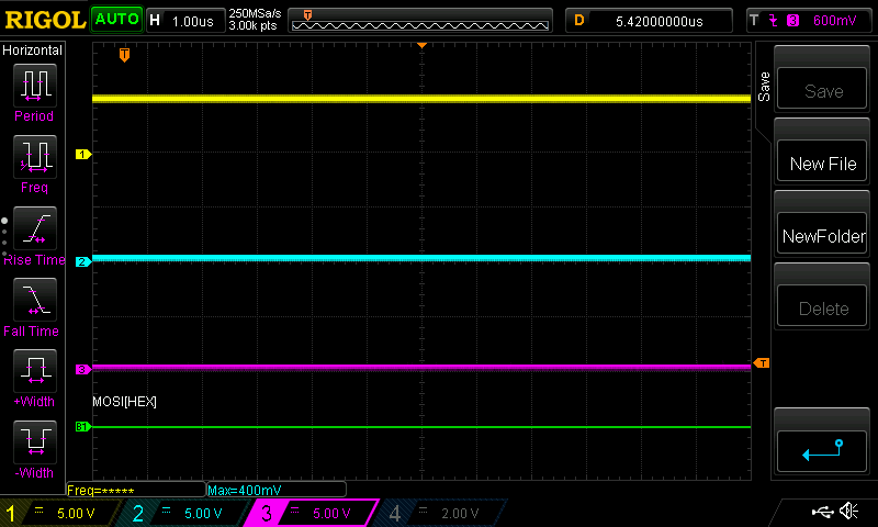
I'm using the Arduino Uno (R3) board to drive an SPI device. What I'm seeing is that MOSI never outputs over 1V. But the odd thing is the logic is on the line. If you look at this capture you can see yellow is SCK, blue is MOSI and pink is chipSelectPin. Reading the bits left to right with the cursor line I can make out 0010 1110 which would appear to be 0x74 which is my first byte sent over SPI. But maybe at this point I'm just seeing ghosts when nothing is there.

The code used to drive this screen capture is inline in this post.
I have found this post: SPI MOSI Output less than 1V. Which seems to be the exact same behavior.
If I put the MOSI pin, 12, to high using digitalWrite it goes to 5V.
The user in that post found their board was dead. So should I assume the same? Or am I making a simple programming error?
#include <SPI.h>

SPISettings nRF8001(2000000, LSBFIRST, SPI_MODE0);

const int chipSelectPin = 7;

void setup() {
  Serial.begin(9600);

  // Initialize SPI
  SPI.begin();

  pinMode(chipSelectPin, OUTPUT);

  delay(100);
}

int16_t readWriteStuff() {
  SPI.beginTransaction(nRF8001);     // Gain control of the SPI bus
  digitalWrite(chipSelectPin, LOW);  // Assert chip select
  SPI.transfer(0x74);                // Send 16-bit command
  SPI.transfer(0xA2);
  digitalWrite(chipSelectPin, HIGH); // Deassert chip select
  SPI.endTransaction();              // Release the SPI bus
  return 0;
}

void loop() {
  int16_t result = readWriteStuff();
  Serial.println(result);
}