Hello to all.
My circuit need to 5v DC and about 1Amp current also I want to provide this power from 220v AC.
I want the smallest circuit for power.Any Idea?
tnx.
A USB mobile phone charger?
If you need the circuit to be tiny and a laptop charger is too big, then here's what you can do:
Feed the AC to a diode full wave rectifier. Then feed that output to a 5.1V Zener diode, a capacitor, and (lastly) a resistor all in parallel.
The output voltage across the resistor will be about 5V DC.
You could solder the circuit onto a small proto board or PCB easy.
Sorry, do you have any circuit for it?
thanks again.
leoncorleone:
Sorry, do you have any circuit for it?
thanks again.
I just described it to you, lol ![]() . You just have to make it.
. You just have to make it.
See attached schematic.

Power_Broker:
I just described it to you, lol. You just have to make it.
See attached schematic.
You have to be joking! The rectified 240 V mains will be directly connected across the 5V zener. This will put very high current through the bridge rectifier and the zener and either the zener or the bridge will fail; probably with a loud bang. If the zener fails then the capacitor and resistor will see the rectified mains and something else will give once again probably with a load bang.
This whole circuit is so silly and dangerous that I have to question your sanity and qualifications.
stowite:
You have to be joking! The rectified 240 V mains will be directly connected across the 5V zener. This will put very high current through the bridge rectifier and the zener and either the zener or the bridge will fail; probably with a loud bang. If the zener fails then the capacitor and resistor will see the rectified mains and something else will give once again probably with a load bang.This whole circuit is so silly and dangerous that I have to question your sanity and qualifications.
Ahhh, yes. It should be isolated with a step down transformer. Forgive me for the mistake, you are right, sir.
If budget allows then why not use this tiny little AC 220v to DC 5v module? it cost me about 4$ and it easily fits on my PCB and breadboard. ![]()
module name Hi-Link HLK-5M05
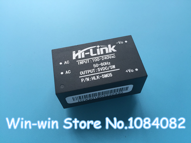
It has a built in transformer and capacitors, in case you're wondering if it's just a cheap 4 rectifier diode inside that tiny box.
MarkT:
A USB mobile phone charger?
lot cheaper
Noobian:
If budget allows then why not use this tiny little AC 220v to DC 5v module? it cost me about 4$ and it easily fits on my PCB and breadboard.module name Hi-Link HLK-5M05
I think that module can run at 5V, 0.6 Amp continuously. The OP reckons they need 1 Amp.
You can take the circuit out of one of these, it's pretty small
| Input Voltage | 100V-240VAC |
|---|---|
| Frequency | 50-60Hz |
| Output Voltage | 5V |
| Output Current | 2A |
Switching DC Wall Power Adapter 5V / 1A - dipmicro electronics 1A
Switching DC Wall Power Adapter 5V / 2A - dipmicro electronics 2A

Thanks everyone.
I have another question.
What kind of Transformer is used in below converter?
This is a 220v AC to 5v DC converter.

tnx
Power_Broker:
Ahhh, yes. It should be isolated with a step down transformer. Forgive me for the mistake, you are right, sir.
It will still go BANG. Even if the AC source in your diagram is the secondary of a step-down transformer, you have no current-limiting resistor for the Zener diode, so it will die, then the full rectified voltage will be available at the output, probably murdering anything attached.
And even with a series resistor, this circuit is nowhere near suitable for an output current of 1A.
leoncorleone:
Thanks everyone.
I have another question.
What kind of Transformer is used in below converter?
This is a 220v AC to 5v DC converter.
tnx
Judging by the size of the transformer, that would be a switching converter, and the transformer would be a high-frequency step-down transformer.
I agree with CrossRoads, pulling the guts out of a commercial 240VAC to 5VDC 2A switching converter is probably the best way to go.
leoncorleone:
Thanks everyone.
I have another question.
What kind of Transformer is used in below converter?
This is a 220v AC to 5v DC converter.
It's just a 2 coil transformer.
Does somebody have any circuit for a switching converter like that?I want to make one of this.
tnx
leoncorleone:
Does somebody have any circuit for a switching converter like that?I want to make one of this.
tnx
You clearly do not have the knowledge to safely design or build a circuit that connects to the mains.
It will be easier, cheaper and safer to do as CrossRoads suggested.
OldSteve:
You clearly do not have the knowledge to safely design or build a circuit that connects to the mains.
You're right.But I want to know more about it.
leoncorleone:
You're right.But I want to know more about it.
Look up switch mode power supply, or switching regulator power supply, buck converter.
But be really careful. Even with that particular module you showed before, one side is potentially dangerous level of voltage (and power). So that's potentially dangerous in itself. But then, if the module isn't designed properly, or bad quality....then even the low voltage side can turn dangerous.
Southpark:
I think that module can run at 5V, 0.6 Amp continuously. The OP reckons they need 1 Amp.
its a 1amp module