facing a problem with a Robotic hand using nRF24L01 project.

This is a my first project and my first post as well.
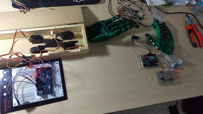
I am working on a project "robotic hand", using an Arduino Mega, 5 servo motors (mg995), nRF24L01. (This is the first part).

A glove, 5 flex sensors, Arduino Uno, and nRF24L01.

I have gone through almost every tutorial and every project similar to mine using the nRF24L01, but nothing seems to work. I couldn't understand the nRF code, besides it doesn't to function the way it's supposed to be. Can someone help me through please?

I would really appreciate it.

  • I am using the NRF24L01: same color of wires with the Mega and Uno.
  • I am using flex sensors with a 10kohm resistors. ( I just wired two of them so the wiring would be clear)
  • I'am using a 9V battery to supply the Mega and a 9V battery to supply the servos as well, but I did not plug them in the pics.
    I have tested the servos and they are doing well, shaking and acting strange sometimes but that's something that I can work on later on.

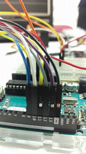
The wiring in the Mega's circuit:

  • Blue represents "Ground"
  • Red represents "5V"
  • Orange represents digital pins "from 2 to 6"

When it comes to flex sensors I have tested them and they are giving me values.

Here s the link from where I got to wire the NRF24L01: http://howtomechatronics.com/tutorials/arduino/arduino-wireless-communication-nrf24l01-tutorial/

I have tried this code, I am not quiet sure how correct it is and I don t know how to make the same thing for "5" servos.

//The Reciever. 
#include <SPI.h>
#include <nRF24L01.h>
#include <RF24.h>
#include <Servo.h>
RF24 radio(9, 10); // CE, CSN
Servo myServo;
int angle ;
const byte address[6] = "00001";

void setup() {
Serial.begin(9600);
myServo.attach(2);
radio.begin();
radio.openReadingPipe(0, address);
radio.setPALevel(RF24_PA_MIN);
radio.startListening();
              }
void loop() {
Serial.println(radio.available()); //Just checking if connects to the other 
NRF or not.
delay(500);
if (radio.available()) {
radio.read(&angle, sizeof(angle));
myServo.write(angle);
Serial.println("angle  " + angle);
  }
}
//The Transmitter.
#include <SPI.h>
#include <nRF24L01.h>
#include <RF24.h>
const int FLEX_PIN = A0;      
int angle;
RF24 radio(9, 10); // CE, CSN
const byte address[6] = "00001";
void setup() {     
Serial.begin(9600);
pinMode(FLEX_PIN, INPUT);
radio.begin();
radio.openWritingPipe(address); // 00001
radio.setPALevel(RF24_PA_MIN);
radio.stopListening(); //sets module as transmitter
 }
void loop() {
int flexADC = analogRead(FLEX_PIN);
angle = map(flexADC, 600, 900,360, 540);
Serial.println(flexADC);
Serial.println(angle);
delay(200);
radio.write(&angle, sizeof(angle));  
}

(I have changed the wiring of the nRF in the Mega, where it is wrong in the pic I have uploaded.)

and a 9V battery to supply the servos as well

You need to stop doing THAT.

I have tried this code, I am not quiet sure how correct it is and I don t know how to make the same thing for "5" servos.

Why would you want to use "5" servos? Seems to me that you'd want to use 5 servos.

pinMode(FLEX_PIN, INPUT);

The pinMode() function is for digital pins. You do not connect flex sensors to digital pins.

int flexADC = analogRead(FLEX_PIN);
angle = map(flexADC, 600, 900,360, 540);

Why is flexADC local to loop() (as it should be) while angle is global? What other function could possibly care about the angle value?

Serial.println("angle  " + angle);

Grab your calculator. ADD the value that you sent and the string "angle ". Show us the result.

Thank you.
fixed it all.
What should I do best when it comes to supplying the servos ? (instead of having the 9V battery)
and, how can I send data of each flex to each servo?

What should I do best when it comes to supplying the servos ? (instead of having the 9V battery)

Run down to your local hobby shop. Look at all the stuff that uses servos, and see how they are powered. Big, beefy batteries.

and, how can I send data of each flex to each servo?

If you invited 5 friends to join you at the ice cream shop, how would you keep the orders straight? "Tom wants vanilla; Bob wants chocolate; Sally want mint chocolate chip; Dan wants strawberry; Mike wants peach."

See the delimiters between the orders (the ; )? See the one at the end that says that the list is complete (the . )?

You send data the same way. Send 5 values every time, with a known delimiter between them, if you send the data as text.

If you send the data as binary, put the 5 values in an array. Then, no delimiters are needed.

You're trying to solve a bunch of different problems in this project. Getting the nRF24L01+ to work with the Arduino is separate from powering the motors, which is separate from properly connected and reading the flex sensors (I assume that you're trying to build a sort of "bionic" remote hand here, cool btw). Focus on each problem separately, then put it all together.

I'm working on a somewhat similar project myself that also involves nRF24L01+ boards. It's relatively easy to use, once you figure it out, but it's a bit confusing at first. Obviously make sure to connect its pins to the proper Arduino pins (e.g. MOSI, SCK, etc.). You'll need the latest nRF24L01+ library installed, and to put the proper initialization code in your sketch, on both the robot arm and controller Arduinos. Also, very important, the nRF24L01+ MUST be powered with 3.3v, NOT 5V, which may well fry it. You can probably get away with using the Arduino's 3.3V pin. Finally, figure out how to actually code and process the transmission and reception of the data "payload" between the two boards.

You'll also need to figure out how to power the motors, and the Arduinos. Setting up the flex sensors should be the easiest part. Good luck!

To power servos, a useful rule of thumb is "1 Ampere per servo", so find a power supply capable of providing 5 Amperes at 5-6V and use that just for the servos. Connect all the grounds together.

Never power a motor or servo from the Arduino as that will cause the Arduino to malfunction, or even damage it.

I agree with the above advice. Get every part of the project working separately before you start putting the pieces together.

Thank you very much.
I'am learning multiple things, thanks to your comments.
:smiley:

Try to calibrate the flex sensors first and check the max n min values.
Refer this video HOW TO CALIBRATE FLEX SENSORS USING ARDUINO - YouTube