I didn't have a BC337 so I used a BC546 instead. I connected a 6 ohm speaker from an old portable radio/cassette player.
It worked great in that it gave nice loud amplification of the tones from the Tone library. Measuring the input signal (from the Arduino pin, in yellow) compared to the transistor collector (blue) shows the amplification isn't perfect, but not too bad.
Now my questions are:
What is the purpose of the amplifier? Impedance-matching? Current amplification? Voltage amplification?
Is the ringing around the rise and fall expected? Could it be improved somehow?
Are there any "gotchas" in there? Like, drawing too much current through the transistor, or something?
If I wanted to implement a volume control, what would be the recommended way of doing that?
Is the purpose of the 100K resistors to bias the transistor base?
What is the purpose of the 10 ohm resistor? To limit current?
Is the purpose of the 2.2K resistor for impedance-matching?
What is the purpose of the amplifier? Impedance-matching? Current amplification? Voltage amplification?
Impedance matching and current amplification is the save thing so a bit of all of them.
Is the ringing around the rise and fall expected? Could it be improved somehow?
It is due to the inductance of the speaker, it can be improved by a better transistor or amplifier
Are there any "gotchas" in there? Like, drawing too much current through the transistor, or something?
Yes it is quite a simple amplifier. I would include a 0.1uF cap between the pin input and the amplifier input.
If I wanted to implement a volume control, what would be the recommended way of doing that?
Put a pot directly on the output and connect the wiper through a cap to the input.
Is the purpose of the 100K resistors to bias the transistor base?
Yes
What is the purpose of the 10 ohm resistor? To limit current?
Yes
Is the purpose of the 2.2K resistor for impedance-matching?
No, it is isolating the bias circuit from the DC effects you get from the input pin, that is why I would use a cap because that removes it compleatly
I like that ABC guide a lot, but I would not use this circuit. I even think it is really bad.
If the output pin of the Arduino is not set as output, the two 100k resistors will turn the transistor on a little.
The two 100k resistors makes the amplification a little analog, but the Arduino output pin is purely digital.
So I would remove both 100k, and perhaps add a flyback diode over the speaker.
Nick, you can't rely on the measurements. The BC546 can do 100mA, and this circuits requires 278mA. The BC337 is a transistor that can handle 800mA.
I read the datasheets for the maximum current of the transistors.
The current is 5V / (10 + 8 ohm) = 278mA, assuming no voltage drop of the transistor and the transistor being fully on.
At 278mA the BC337 has Hfe of about 250. So the 2k2 will turn it into saturation.
The NPN BC337 is an old transistor.
The NPN BC639 is a little newer, it can do 1A, and it has the BC640 as complementary PNP.
These are the prices in my country (a piece)
BC547B : 5 euro cents
BC546B : 6 euro cents
BC337 : 10 euro cents
BC639 : 20 euro cents
@ Mike the only point I'd disagree with you on is the input resistor and that is to limit the base current to a safe value. 2K2 is 50 times the "bias'" resistors and as such will have little effect on their operation.. A .1 to 1uF cap (depending on the desired low frequency response) should work well with the 30 k or so input impedance presented at the base lead.
Ciao,
The initial intentions were to make an amplifier as simple as possible (with only 1 cheap transistor).
There are several modifications that can be done, especially include a capacitor between the input pin and the amplifier.
In the next few hours, i check it and i put an optimized one (with volume control :D)
PighiXXX
Thanks for the support!
Checking diagrams is a good thing from you because for surely there are people better than me in this forum and together we can do a good job for everyone.
@pighixxx - I am testing to check my knowledge is sufficient to understand your diagrams, and if things don't work perfectly I'm keen to understand why. Perhaps it's my fault.
That amplifier is a "Class A" amplifier. Theoretically, it is supposed to be biased so that with no signal, the collector sits at about 1/2 Vcc (so that it can swing UP to VCC and DOWN to GND).
The resistors on the base circuit create a bias (base current * beta = collector current) to keep the transistor conducting (that is, in a Class-A mode).
The top bias resistor is connected to the collector to provide NEGATIVE feedback and stabilize the bias. That is, if the bias is too "strong", the collector will go lower and decrease the base bias, thereby self-stabilizing the circuit.
I would try this for fun: Remove the 2.2K resistor between the Arduino and the transistor base and replace it with a 1 uF (not critical) capacitor (positive side to the transistor base).
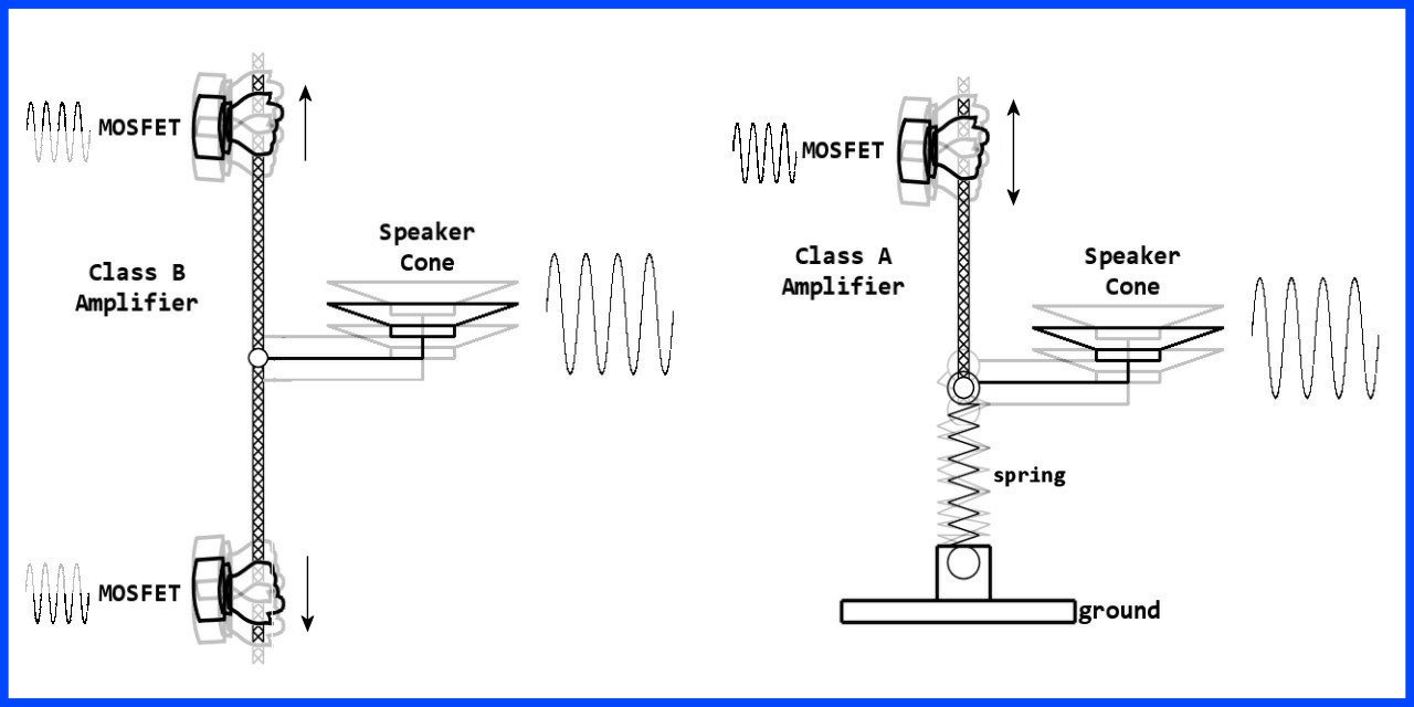
Here's a sketch I made for another guy a while back to explain Class A and Class B amplifiers. Hopefully this will help:
(edit to add): If you take the "Class A" sketch and invert it so that the "spring" is at the top, that is basically the same as your circuit - and BJT vs MOSFET doesn't matter - they both do the same jobs - albeit in a different way.
(edit to add more): Notice that the Class B amplifier "rope" needs to be taut, otherwise there will be a small "dead zone" where the speaker doesn't move. The tension on the rope is the bias, and if there isn't enough bias and the rope is loose, the dead zone on the speaker is called "crossover distortion".
Hey Nick,
This is the amplifier I have in my fencing scoring machines, driven by a burst of Tone to make a nice two-tone warble when a touch is scored (sounds like cell phone ring).
Can probably replace the MOSFET with NPN too. (The IFR3707Z apparently went obsolete right after I bought a sleeve of 10.)
When input is Low, transistor is off, cap keeps any DC from flowing into the speaker, but the yellow wire sits high.
When input is High, transistor turns on, pulls cap low to move speaker one direction.
When input goes back high, the cap goes high and the transition thru the cap drives the speaker the other other direction until the cap charges up again.
So Tone makes a nice sound with this MOSFET and speaker. The 68 ohm resistors were an attempt at high/low volume control - my wife says it is still way too loud.
Well, actually, not "quite" a Class A design. Class A is intended to bias the transistor
into its linear region of operation, but you'll never get that with the ckt as shown.
It looks like the person who designed it had the intent of Class A, but you would need
a resistor in the emitter lead, so the 100Ks on the base have something to bias in
a stable fashion. As it is, they simply turn on the transistor, and whether or not the
collector sits at Vcc/2 is strictly a factor of the hFE [beta] dc current-gain of the
transistor.
But there is a much more serious problem with this design, namely that there will be
a constant dc-bias on the speaker and a non-trivial amount of dc-current continually
running through it. Not good, the speaker can burn up. Instead, speakers should be
AC-coupled through a large capacitor with a ckt like this - ie, attempted Class A. And
unfortunately, that cap needs to be a large value, eg 220 uF, to get proper low-
frequency response, since the speaker impedance is so small.
Also, with a proper Class B, as Krupski mentioned, the positive and negative drive
ckts will be adjusted so the DC current through the speaker is 0, so that takes care of
the problem of continuous current burning up the speaker.
Advice - throw this ckt away, use something better.
oric_dan:
But there is a much more serious problem with this design, namely that there will be
a constant dc-bias on the speaker and a non-trivial amount of dc-current continually
running through it.
Why is there that current (which incidentally the scope trace appears to agree with)?
If the transistor is "off" it shouldn't be conducting, should it? Or does the biasing keep it on? I guess it must be that, because on the scope it looks like when the input signal is off, the output signal is around 2.2V.
Yes, that's it. If you remove the 100K pullup, and keep the 100K pulldown - to keep
the transistor turned off, and then capacitively couple the input signal, as others have
mentioned, then the transistor will stay off when no signal is present. Then, you also
don't need to capacitor-couple the speaker.
However, you'll only ever get square-wave outputs [ie, rasty sounding things] from
your speaker.
It is possible to get sweeter sounding audio using the Arduino. Would require going to
a true Class A amplifier ckt [or more complex Class B, etc, as Krupski mentioned], and
then using high-frequency PWM, modulated at a lower audio rate, and then using
low-pass filters ahead of the amplifier to smooth out and anti-alias the PWM.
Interesting. In this particular case I am feeding in square waves anyway, so that's no great loss.
I mean, you can get amplifier chips for a couple of dollars if you want proper amplification, but I was leaning towards getting the square wave tones out of the thing to be loud enough to hear, and not damage the output pin.
So your suggestion of adding the capacitor, and removing the resistor, could well achieve that with minimal effort.
BTW, if I remove the resistor between collector and base, wouldn't the capacitor need to have the positive side (if it had one) to the Arduino output pin, and not the transistor base, as the output pin would be more positive?
Nick,
Wire it up like my Mosfet example. The cap keeps the DC out of the speaker, and the sound is nice.
Here's the heart of the code:
// info on alarm sound
#include "pitches.h"

// notes in the melody:
int thisNote = 0;
int noteDuration = 0;
int pauseBetweenNotes = 0;
int melody[] = {
  NOTE_C6, NOTE_A5, NOTE_C6, NOTE_A5, NOTE_C6, NOTE_A5, NOTE_C6};
// note durations: 4 = quarter note, 8 = eighth note, etc.:
int noteDurations[] = {
  12,12,12,12,12,12,4};
  // create a warble once
  for (thisNote = 0; thisNote < 8; thisNote++)
  {
    // to calculate the note duration, take one second
    // divided by the note type.
    //e.g. quarter note = 1000 / 4, eighth note = 1000/8, etc.
    noteDuration = 1000/noteDurations[thisNote];
    noTone(6);       //apparent known bug - need this for the tone to play next.
    tone(6, melody[thisNote],noteDuration);
    // to distinguish the notes, set a minimum time between them.
    // using the note's duration + 10%:
    pauseBetweenNotes = noteDuration * 1.10;
    delay(pauseBetweenNotes);
    // stop the tone playing:
    //  noTone(6);
  }
Krupski:
I would try this for fun: Remove the 2.2K resistor between the Arduino and the transistor base and replace it with a 1 uF (not critical) capacitor (positive side to the transistor base).
0.33 uF capacitor added in series with the 2.2K resistor:
0.33 uF capacitor added instead of the 2.2K resistor: