Hi, I want to control a pump using a transistor and my Arduino Mega 2560. I used this tutorial to wire the pump (basically just a 3-5V DC motor in a casing) to the transistor, adding a flyback diode and connecting the base of the transistor to my Arduino. I'm using a PN2222A transistor and a 1N4001 diode. Both the Arduino and the pump are powered by a power source with 5V and up to 12A. The Arduino is powered via the 5V and GND pins.
The wiring works and the pump runs but with much lower current than needed for pumping water to the desired height. If I connect the pump directly to the power source it works just fine. I tried measuring it with my multimeter and got a current of around 70mA when connected directly to the power source and only around 35mA with the above circuit. Both times I measured the current by connecting the multimeter in line between the motor GND pin und the power sources GND.
Do you have any idea why the circuit is reducing the current the motor is drawing? Do I have to use another type of transistor or is the wiring wrong?
(Also, the transistor is getting really hot, too hot to touch. But I read that is to be expected for power transistors switching on and off motors.)
I don't see a current limit resistor in the transistor base circuit, about 220 Ohms, hope you bought some spares. Also, are you sure the transistor is a P2N2222? The pinout is reversed from a "standard" 2N2222.
You will damage the Arduino if you don't have a suitable resistor between the port pin and the transistor base.
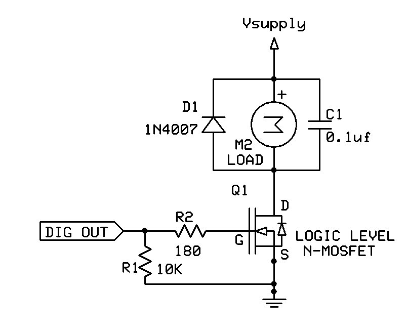
Brushed DC motors draw starting current that is up to 10 times higher than the running current. You need a better transistor -- use a logic level N-MOSFET instead (also with a resistor between the gate and the port pin).
@Paul_KD7HB: I got it from ebay, so I'm not sure what the exact specifications are but I read something between 200mA and 600mA on different sources.
@outsider: I added the resistor to the base but how do you know how big it should be? On its back it says CTPN2222A, that's all the information I got. So it should be a simple PN2222 transistor
@jremington: I know MOSFETs are preferred for this kind of task, but I don't have any at hand. But shouldn't it work with a transistor as well?
I added 220 Ohms at the Base but the motor is still not able to draw suitable current.
morrisonandboyd:
You will get a 0.6-0.7 volt drop through the transistor when fully on.
A TIP-120 darlington is a better power transistor.
Make that ~0.1volt for the PN2222 (with the right base current).
A TIP120 has >=0.7volt saturation because of the darlington configuration.
Not a good choice below a few hundred milliamps.
A 220ohm base resistor and a PN2222 should work.
Maybe OP should post a real picture of the setup.
Note the TWO mistakes in the Fritzing picture.
Leo..
Was looking at the saturation graph of the ON Semiconductor PN2222 datasheet.
The table lists 0.4volt max with 150mA collector current and 15mA base current.
OP mentions a max load of 70mA. Sounds low for a 5volt 'pump'.
Leo..
@Wawa: Thanks for pointing out I made a mistake in the Fritzing, the picture below should show the corrected one. Inverted the diode and connected the collector to the cathode of the diode.
Below are pictures of the real setup. The circuit is built six times in parallel to power six pumps (should've tested it more rigorously before soldering it all, but just checked if it worked and not the power) but just the first pump is connected to the circuit. The Fritzing is just a breakdown of the problem. When rebuilding the circuit on a breadboard and powering the motor from the Arduino 5V supply I got the same issue. Powering the motor without the circuit from the Arduino 5V supply works fine.
Thank you! The MOSFET will not reduce the voltage or current flowing through like the transistor?
And what for are the 10k resistor and the capacitor?
Edit: Also I just remember that I've got some L293Ds lying around. Couldn't I use them to run the motors? Or is a MOSFET still safer and a better choice?