And here is the code:
/* Juan Ramón Muñoz Rico
Escuela Politécnica Superior
Campus Viriato de Zamora
Universidad de Salamanca
http://dim.usal.es/eps/mmt
*/
/*
===================================74HC595===================================
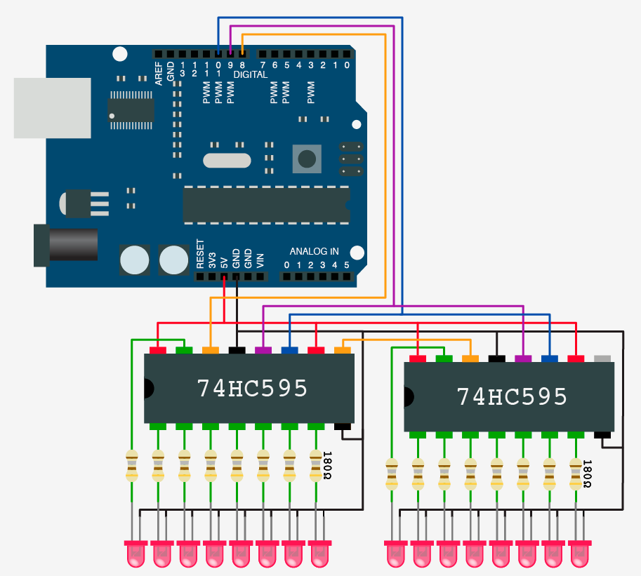
A continuación te pongo cómo tienes que conectar el primer chip al
Arduino. Ten en cuenta que los pines se numeran del 1 al 16 desde el
inferior izquierdo (1), en el sentido contrario al movimiento de las
agujas del reloj, viendo la muesca del chip a la izquierda, terminando así
en el 16, en la esquina superior izquierda, que es Vcc.
*/
/* pin 12 (ST_CP) on the 75HC595 */
int latchPin595 = 6;
/* pin 11 (SH_CP) on the 75HC595 */
int clockPin595 = 7;
/* pin 14 (DS) on the 75HC595 */
int dataPin595 = 8;
/* How many of the shift 74hc595 - change this */
#define number_of_74hc595s 5
/* do not touch */
#define numeroDeReles number_of_74hc595s *8
boolean rele[numeroDeReles];
/*
===================================74HC165===================================
A continuación te pongo cómo tienes que conectar el primer chip al
Arduino. Ten en cuenta que los pines se numeran del 1 al 16 desde el
inferior izquierdo (1), en el sentido contrario al movimiento de las
agujas del reloj, viendo la muesca del chip a la izquierda, terminando así
en el 16, en la esquina superior izquierda, que es Vcc
El pin 15 lo he puesto a 9 y rula, así que así queda.
*/
/* pin 1 (PL) on the 75HC165 */
const uint8_t pLoadPin165 = 10;
/* pin 2 (CP) on the 75HC165 */
const uint8_t clockEnablePin165 = 11;
/* pin 9 (Q7) on the 75HC165 */
const uint8_t dataPin165 = 12;
/* pin 15 (CE) on the 75HC165 */
/* const uint8_t clockPin165 = 9; */
int numeroderele;
int valor0o1;
/*
const uint8_t pin_CE(barra) = 15; // to pin 9 of the 1ast chip.
pin 10 of each chip to pin 9 of next chip
*/
/*
==============================Pantalla 20x4·I2C==============================
Conecta los cables SDA a SDA y SCL a SCL, calamar.
*/
#include <Wire.h>
#include <LiquidCrystal_I2C.h>
/* A continuación, el código para poner dos pantallas. */
LiquidCrystal_I2C lcd0(0x27,20,4); /* LCD 0x27 */
LiquidCrystal_I2C lcd1(0x26,20,4); /* LCD 0x26 */
/* Aquí originalmente ponía 0x24. Pues no. Hay que poner 0x3f y rula. */
/*
Nótese la diferencia: uno es 0x26 y otro, 0x27. Diferentes direcciónes
I2C.
Ver el vídeo https://www.youtube.com/watch?v=gBg0OR6Voc8&t=119s
Si es sólo una pantalla, aquí originalmente ponía 0x24.
Pues no. Hay que poner 0x3f y rula.
Ésto último es lo que vale con el I2C que he soldado yo, como se indica en
el vídeo.
*/
/*
=============================================================================
=============================================================================
*/
void setup()
{
/* Serial.begin(115200); */
/*
===================================74HC595===================================
*/
pinMode(dataPin595, OUTPUT);
pinMode(latchPin595, OUTPUT);
pinMode(clockPin595, OUTPUT);
/* reset all register pins */
borra595();
escribe595();
/*
===================================74HC165===================================
*/
pinMode(pLoadPin165, OUTPUT);
pinMode(clockEnablePin165, OUTPUT);
pinMode(dataPin165, INPUT);
digitalWrite(pLoadPin165, HIGH);
digitalWrite(clockEnablePin165, HIGH);
/*
==============================Pantalla 20x4·I2C==============================
Iniciamos el fondo retroiluminado.
*/
lcd0.init();
lcd0.backlight();
lcd1.init();
lcd1.backlight();
/* lcd.noBacklight(); */
/* lcd2.noBacklight(); */
/* Iniciamos las dos pantallas LCD. */
lcd0.setCursor(0,0);
lcd0.print(" Morales del Vino ");//Escribir en la LCD
lcd0.setCursor(0,1);
lcd0.print("Salidas: Expreso ");//Escribir en la LCD
lcd0.setCursor(0,2);
lcd0.print("Destino: Salamanca ");//Escribir en la LCD
lcd0.setCursor(0,3);
lcd0.print("Hora: 15:10 ");//Escribir en la LCD
lcd1.setCursor(0,0);
lcd1.print(" Candelario ");//Escribir en la LCD
lcd1.setCursor(0,1);
lcd1.print("Llegadas: Mercancias");//Escribir en la LCD
lcd1.setCursor(0,2);
lcd1.print("Procedencia: Zamora ");//Escribir en la LCD
lcd1.setCursor(0,3);
lcd1.print("Hora: 04:50 ");//Escribir en la LCD
/* delay(1000); */
}
/*
=============================================================================
=============================================================================
*/
void loop()
{
/*
===================================74HC595===================================
*/
/* cambiaRele(10, LOW); Esto está puesto para probar; se puede borrar. */
/*
===================================74HC165===================================
*/
/* Latch data from input pins into shift rele. */
digitalWrite(pLoadPin165, LOW);
digitalWrite(pLoadPin165, HIGH);
/*
Aquí tienes también que intervenir. En el bucle tienes que cambiar el
parámetro "n" en "i < n". Tienes que poner el número total de pines que
quieres que se lean. Este número será igual al número de chips x 8 (esto
ya es para logsianos).
*/
/* Read all bits from all shift 74HC165 one by one. */
for (int i = 1; i <= 40; i++)
{
if (digitalRead(dataPin165) == HIGH)
{
//Serial.print("1");
numeroderele = i;
valor0o1 = LOW;
cambiaRele(numeroderele, valor0o1);
}
else
{
/* Serial.print("0"); */
numeroderele = i;
valor0o1 = HIGH;
cambiaRele(numeroderele, valor0o1);
}
/* Clock pulse to shift to the next bit */
digitalWrite(clockEnablePin165, LOW);
digitalWrite(clockEnablePin165, HIGH);
}
Serial.println();
}
/*
=============================================================================
=============================================================================
*/
/*
===================================74HC595===================================
*/
void borra595()
{
/*
Set all register pins to HIGH/LOW.
HIGH es que los relés están cerrados (luz apagada).
LOW es que los relés están abiertos (luz encendida).
*/
for(int i = 0; i <= numeroDeReles - 1; i++)
{
rele[i] = HIGH;
delay(50);
escribe595();
}
}
/*
=============================================================================
*/
void escribe595()
{
/*
Set and display 74HC595.
Only call AFTER all values are set how you would like (slow otherwise)
*/
digitalWrite(latchPin595, LOW);
for(int i = 0; i <= numeroDeReles - 1; i++)
{
digitalWrite(clockPin595, LOW);
int val = rele[i];
digitalWrite(dataPin595, val);
digitalWrite(clockPin595, HIGH);
}
digitalWrite(latchPin595, HIGH);
}
/*
=============================================================================
*/
void cambiaRele(int numeroderele, int valor0o1)
{
rele[numeroderele-1] = valor0o1;
escribe595();
/* MUST BE CALLED TO DISPLAY CHANGES */
/* Only call once after the values are set how you need. */
}
Special thanks to Grumpy_Mike and Jobi-Wan for their help and, above all, for their enormous patience with me.