So I've been wanting the ability to monitor and control my old Genie Pro garage door opener and have done lots of internet searches and am looking at using an Arduino board (or boards) to do a few things.
One of my goals is to "piggyback" or "jumper" onto the Genie Pro's existing two (2) travel limit switches for sensor input to the Arduino to get "basic position status" readings of "Open" and "Closed" for the door. I'd rather do this than spend more money on additional sensors, as my main goal is to be a CHEAP as possible.
I was curious and did some multi-meter investigation. Each limit switch is closed by the movement of the door trolley. One stops the motor when the door is fully closed and the other stops the motor when the door is fully open. They each have only one wire connected to them, and they have 7.7v on them continuously until the switch closes. When they close, they simply ground against the frame and that's when the voltage on them drops to 0.0v. Any idea how I can "piggyback" or "jumper" onto the connection for each of these limit switches and somehow reduce the voltage on that jumper wire so I can connect it safely to an Arduino input (5.5v max) (but not alter the voltage that the Genie Pro needs)?
I'm intentionally not specifying any particular Arduino boards to get as much feedback as possible from you guys, but I also want to keep this project as CHEAP as possible for when I tell friends about it.
.
Is that 7.7V AC or DC? If DC, maybe a simple voltage divider, do you have a schematic of the circuitry? Might be in the user's manual or post the model number.
If whatever it is that powers those switches can deliver a bit of current (2-5 mA is enough) I'd prefer an optocoupler to completely isolate the two. No risk of ground loops and other odd effects.
To @outsider I had my multi-meter set on DC when I got the 7.7v. I had checked it first for AC but don't remember the number that displayed except that it was somewhat close to this same number. Maybe 9v (ish) but can't say for sure. I figured if it was AC, and was that low, checking for DC probably wouldn't kill my meter. I've attached the owners manual. It's a Genie Pro CM8600IC (1/2 HP motor) which is usually simply referred to as a CM8600. See page 33 and the switches I'm referring to are connected to terminals 15 and 16 on that page. It looks to me that it's getting power from the secondary winding of that coil which is on the neutral side of the 120v AC circuit. I can't remember, does power on the secondary side of a coil always end up as DC?
If this is DC, I see from the diagram that the RPM sensor is also powered from this same secondary side of the coil and I was already hoping to tap into that RPM sensor (rotary encoder) for a signal to display the percentage that the door is open. I know that's somewhat redundant with what I'm trying to do with the switches (above), but I'm expecting the encoder to not always be spun by the exact same count every time. Maybe it will, but if the sensor is already there, why not use it is my approach. That way, I'll have backup information about the state of the door. Do either of you (@outsider or @wvmarle) see any issues now that you can see the wiring diagram for my GDO that I might have trying to set that up? I was thinking just tap into those and follow other efforts in these forums for connecting an encoder to an Arduino.
To @wvmarle I've heard of optocoupler's, but that's about it. Can you explain what they do and how to use them here? Are they similar to diode's? I have a mechanical engineering degree but that's a far cry from an electrical one. I'm definitely out of my element. But I've always enjoyed dabbling in electric stuff too. This is my first "smart" project though.
@wvmarle Sorry. It's late and I should go to bed. I could have looked that up. Sounds like a good idea. Thanks. Any further direction on the rest of my last reply?
Sorry my posts are so detailed and long, but I've researched and learned some more. All transformers output AC. There's only a DC output if there's also a rectifier attached to the output of that transformer. Also, I've learned that cheap multi-meters like the ones I typically buy won't read RMS AC voltage, but rather have a built in "simple precision half wave rectifier" of their own to make the meter measure AC voltage.
This article about testing for AC on a battery batteries - Measuring AC voltage from DC battery - Electrical Engineering Stack Exchange helps me understand that when your probes are connected in proper polarity as if checking for DC voltage, but actually checking for AC with your meter (on what is actually a DC source), a battery will give false readings! But if you reverse the meter probes (polarity), you would get 0.0v.
So I checked a battery for myself as well as a power brick (transformer) for an electric stapler I had handy and they both gave an AC voltage reading. But when I reversed the probes, I got 0.0v! Which led me to re-check for the "AC" I was reading at the limit switches on my garage door opener with reversed probes and what do you know...I got 0.00v! These are definitely DC voltages! Lesson learned for why some multi-meters are WAY more expensive!
Next I checked the voltage on the terminals of the encoder. The top wire (see picture attached) is a ground. The middle reads 10.15v DC and the bottom terminal reads 4.15v DC when the motor is not running, but those readings drop some when the motor is running.
@wvmarle's idea for optocoupler's for these signals seems like the cheapest way by far to get the voltage I need from these signals. I'm guessing I'll need 2 for the 2 limit switches (right?) but I don't know how many to get for the encoder. Would it be one for each of those 2 encoder terminals that have voltage?
Encoders should put out some kind of a block wave, otherwise there's nothing to count.
You'll need one optocoupler for each limit switch, but this only works if there's enough current available to
operate them (1-5 mA). Switches tend to carry very little current (around 0.1 mA) , too little for an optocoupler.
Not having a complete circuit diagram makes it hard to give suggestions.
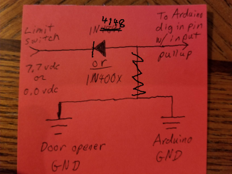
If you are SURE it's DC then this might work, diode prevents 7.7V from getting to Arduino pin, but limit switch can still pull the pin low, don't forget to pinMode the pin to INPUT_PULLUP in setup(). And BE SURE the limit switch voltage is POSITIVE with respect ground.
BTW: That "encoder" looks like a simple pulse generator but can't really tell from picture.
No need to use a Schottky here, a regular diode (1N4841, 1N400x) will do just fine. R1 and C1 are optional, and slow down reaction.
Sharing grounds may or may not work. The problem is we don't know the circuit that connects to the switch. Even if the other side of the switch is connected to the garage opener's ground, a connection may cause ground loops.
An optocoupler is the safest solution (and cheap) but relies on the switch's connection to supply several mA of current, and fair chance that this is not available as it's a switch that's being read.
Now if you could completely disconnect the Genie circuit you would have a simple switch to work with, and problem solved. I guess that's not an option for you.
A final way I'm thinking of is to probe the switch using AC. That way you can use two capacitors (one on either side) to electrically isolate the two sides.
I understand the desire to be cheap but you might blow up the garage door controller by making an incorrect connection. It would be very easy to overload its logic power supply and you probably can't replace that part on its own.
Make your own switches. Two pieces of metal screwed to a wood block can be a switch.
Salvage a switch out of old equipment. Printers and photocopiers have a lot of nice photointerrupter switches inside them.
If you have an old-and-broken garage door controller because you already screwed up one, then extract its switches.
@wvmarle I checked for current on the wire for one of the limit switches with my clamp meter while the motor was running (and not) and the current was a maximum reading of 0.63 amps (see attached picture). I had the "Peak Hold" button set each time I ran the test. But please understand, that reading only happened once further away from the switch than most of the readings I took and it was near a wire connector someone put in that line for some reason (I bought the house with this GDO). I'm very suspicious about that reading because I tested it several times close to the limit switch and the typical amp draw was more like 0.10 to 0.20 amps or anywhere in between. Once I got 0.4x amps. It was actually varying quite a bit from test to test. My meter was set on 20 amps (see attached picture). My question for you is that since 0.100 amps is = 100ma I'm wondering if maybe it does have enough power after all, or could you have possibly been thinking in amps but instead wrote mA when you gave those numbers for current typically found on a switchs. What do you think? Could this wire run an optocoupler after all? If not, could I get power to the optocoupler another way and still use it for the signal?
Also for @wvmarle, regarding your post #9, I had come across this video that seems to support what you were saying about using only a diode on the limit switches, but the subtitles in the video are difficult for me to follow and it doesn't seem to give "the whole story". At 1:30 he mentions a diode connected to the limit switch. If you have about 2 minutes, watch this and give me your thoughts. My Genie looks to be almost exactly like this one (except with a black case). Sonoff TASMOTA garage remote limit switch hack - YouTube If a diode alone will work, how is it that the diagram @outsider provided would be modified? I'm confused on that.
@outsider, thanks for the diagram, and your "BTW" comment encouraged me to look closer at the wiring diagram I attached to post #3 from the owners manual (page 33). I didn't see this until now, but it shows that the orange wire is the signal wire. That's the bottom terminal in the picture I attached to post #7. Since that terminal measured 4.15 vdc as I mentioned in post #7, do you guys think that signal will be okay to connect to the Arduino directly? Seems logical to me.
@MorganS, thanks for the input. I won't ignore your suggestions if my initial direction doesn't pan out, but I just got excited when I realized that there are plenty of existing signals to do what I'd like to do already on the GDO and the other posts seem to be leading me in the "hopeful" direction. I may not be an electrical engineer, but I'm not afraid to screw something up, and I do realize that I need to seek advice from you guys before I attempt something like this. I will probably have everyone exhausted before I jump in, but I don't mind asking questions as long as I don't bother any of you too much in the process.
0.63A seems way too high for a limit switch. I don't trust any clamp meter. They are very sensitive to stray magnetic fields. I suspect measurement error.
Try it with the optoisolator. It is a fun thing to learn.
In the Arduino world, a typical switch configuration has a 10-100k pull-up resistor, that gives 0.5-0.05 mA of current. Enough to detect whether a switch is closed or not. In some situations this may be increased to a few mA.
Adding an optocoupler in parallel to the switch wired that way WILL of course change the switch's readings, as it's also in series with such a pull-up resistor. That may in turn mess up the existing circuit. Your switch may have been wired differently, of course.
To measure the current, you best use a regular multimeter. While the switch is open connect the probes to either side of the switch, effectively closing it (the multimeter in current mode offering a very low resistance path). When you do this, the switch should be read as closed, and the multimeter will give you the current flowing through the switch in that state.
outsider:
If you are SURE it's DC then this might work, diode prevents 7.7V from getting to Arduino pin, but limit switch can still pull the pin low, don't forget to pinMode the pin to INPUT_PULLUP in setup(). And BE SURE the limit switch voltage is POSITIVE with respect ground.
BTW: That "encoder" looks like a simple pulse generator but can't really tell from picture.
Lose R1 and C1, use software debounce, simpler hardware The diode doesn't need to be
schottky, a common-or-garden 1N4148 will be fine. A modest value of R1 like 4k7 can be
used for more protection (it needs to be an order of magnitude lower than the internal
pullups).
Okay, no jokes about having so many cheap meters or my ignorance in reading them! LOL!
But... can you guys tell me which scale to read from on my other cheap meter (but not a clamp type)? The dial is set on 0.5mA for both readings. One picture is with the switch closed, but which scale do I get the reading from? Is this 8mA * 0.5 = 4mA, or is it 40mA * 0.5 = 20mA. At first I thought 4. Now I'm thinking 20, but selection of the scale to read from has me confused and neither number is in line with what you guys had me expecting. The door did stop when the switch closed even though the current was going through the meter. I took a video, so if that would help let me know. The 2nd picture is with the switch open (showing 0). The 3rd picture is what I "think" you guys are saying to do with the circuit diagram. Is this correct?
DO NOT APPLY VOLTAGE TO THE METER ON A CURRENT RANGE, not even 0.1V! The fuse will blow!
You're on the 0.5 mA full scale setting, the needle is on 40 of a 50 scale, so 40 / 50 * 0.5 = 0.4 mA.
You have a wire from the input pin wire to ground, that's grounding out your signal, remove it.
When that is done, put your meter on the 50 DC volt scale first, put black lead to ground, red lead to input pin, if less than 10V, switch to 10V range, you should see about 5V when the switch is open and near 0 when switch closed.
Thanks @outsider. Your caution is directed towards the right person that's for sure! For what it's worth, I at least knew that when checking current, the meter must be connected in series with the lead from the switch. You should ask me how I know. LOL
I had disconnected the lead between the GDO and the switch and then placed my meter in series between them. That's more obvious in my video here. But again, no jokes about my original mis-reading of the scale (or my redneck accent). LOL! operating both ways 20190114_204104.mp4 - Google Drive
I think I'm still confused some after your revision to my drawing. Does this new drawing make sense?